Performance Verification
1780R-Series Service Manual
4–23
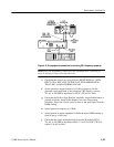
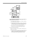
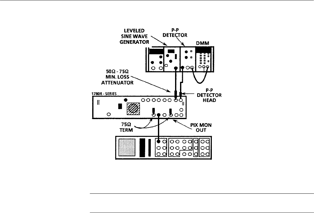
Figure 4–8: Test equipment connections for checking CH A frequency response
NOTE. Leave the termination connected to the PIX MON OUT connector for
steps 11 through 15 unless directed otherwise.
e. Check that the controls are set as follows: RIGHT DISPLAY–WFM,
INPUT–CH A, REF–EXT, FILTER–FLAT, WFM HORIZONTAL–
TWO–LINE, and WAVEFORM GAIN–Off.
f. Set the generator output frequency to 50 kHz (reference). Set the
generator output amplitude so the waveform CRT display is exactly
714 mV or 100 IRE in amplitude for NTSC (700 mV for PAL).
g. Check that the Peak-to-Peak Detector Amplifier +Input Enable button is
pressed in and the –Input Enable button is set to the Out position
(disabled). Adjust the +Level control to turn on the green light. Note the
DMM reading.
h. Set the generator frequency to 1 MHz.
i. Set the generator output amplitude to obtain the same DMM reading as
noted in part g. of this step.
j. Check that the signal amplitude displayed on the Waveform CRT is
714 mV or 100 IRE in amplitude within ±7.1 mV for NTSC (700 mV
within ±7.0 mV for PAL).


