Theory of Operation
3–78
1780R-Series Service Manual
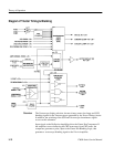
Horizontal and vertical readout (from the MPU), X and Y output, and picture
monitor sweeps are input directly to the switching circuit for display on the
Vectorscope CRT.
Input signal switching to the Deflection Amplifiers is Master MPU controlled in
response to front-panel switching and touch screen menu selections.
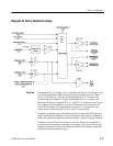
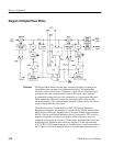
R-Y and B-Y Amplifiers. The low-pass filtered outputs of the Demodulators drive
identical inverting operational amplifiers, U216 (R-Y or V) and U735 (B-Y or
U). Amplifier gain is approximately 11.
A small amount of R-Y (V) is fed into the B-Y (U) Amplifier input through
R736 to provide + and – range for the Orthogonality adjustment, R511.
RY Buffer. U803 is an inverting operational amplifier used as a buffer. When R-Y
sweep is selected for the waveform monitor, the R-Y (V) Buffer drives the
Vertical Amplifier with demodulated chrominance. Stage gain is approximately
0.3.
Low-Pass Filter and Luminance Amplifier. Luminance signal from the waveform
monitor is filtered by a four-pole low-pass filter employing Q145 and Q246 as
its active elements.
Filtered luminance drives an externally-compensated inverting operational
amplifier, U150. Vector horizontal positioning voltage is applied to its + input as
an offset. C153 is a delay adjustment that matches the luminance signal delay to
the chrominance signal processing delay.
Switching. In addition to the R-Y (V), B-Y (U), and Y that are displayed in
Vectorscope modes, alpha numeric readout, XY, and picture monitor deflection
sweeps need to be input to the Deflection Amplifiers. Signals are switched to
their prospective amplifiers through DIP switches U415, U432, and U534. U415
makes one of four possible selections: R-Y (V), vertical readout elements,
picture monitor vertical (field) sweep, and the X-axis voltage.
The Horizontal Deflection Amplifier has five possible inputs through U432 and
U534. In addition to BY (U), there are horizontal readout elements, picture
monitor horizontal (line) sweep, Y-axis voltage, and luminance.
Readout Gain adjustments (R833 for the vertical and R836 for the horizontal) are
located in the compensations at the switch inputs.
U333 and U345 are multiple OR gate packages driven by Master MPU control
lines that provide the switch control logic.
Circuit Theory


