Theory of Operation
1780R-Series Service Manual
3–19
DC Restorer and Reference Selection. Data for the reference and DC Restorer is
latched in by U1506. This latch controls input coupling and DC Restorer
operation along with the internal/external reference selection.
Filter Selection. The encoded 4 bits of filter selection data is latched in by U905.
U815 is a logic array, controlling filter selection and calibrator timing. U720 is a
3:8 decoder outputting the filter selection signals for Diagram 5. Four data bits
on Latch U905, F0 through F3, have all the filter selection data encoded in them.
See Table 3–3. Logic for multiple filter displays, such as Flat/Lum, is in a state
machine in U815.
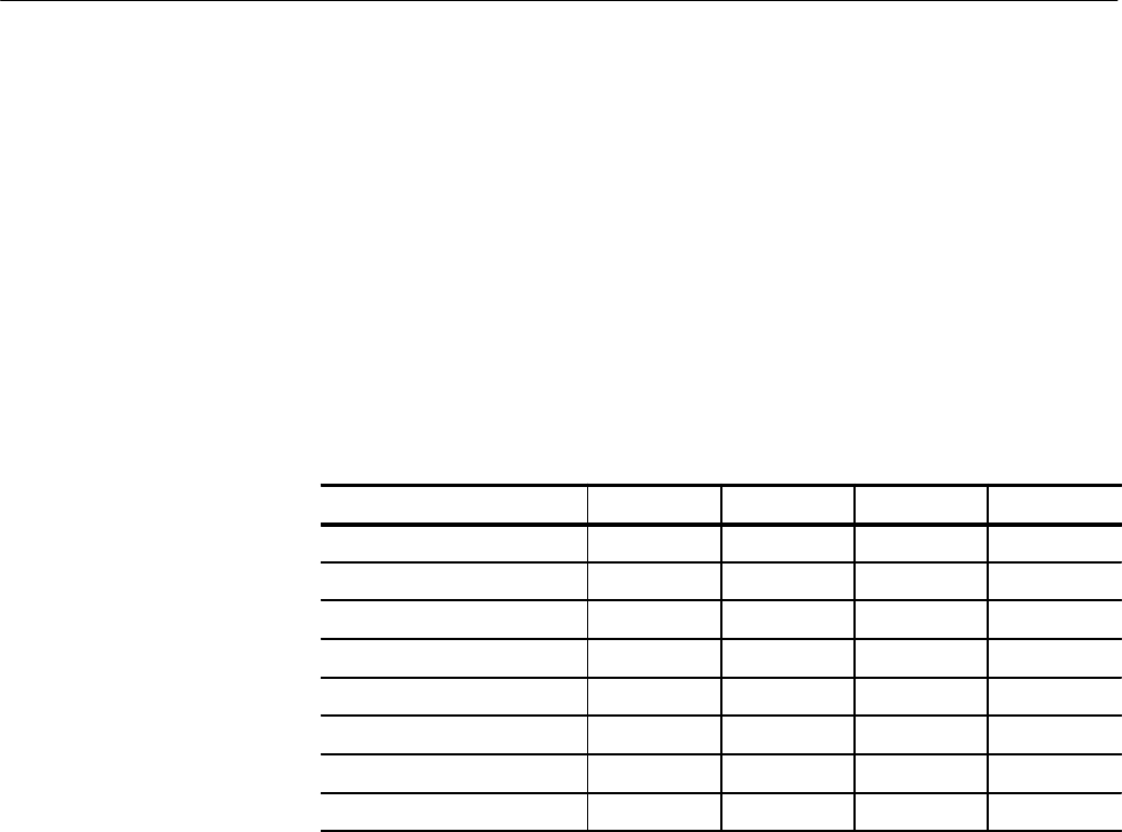
Table 3–3: Filter Selection Logic
Filter(s) F
0
F
1
F
2
F
3
FLAT 0 0 0 0
LUMINANCE 0 0 1 0
CHROMINANCE 0 1 0 0
LOW-PASS 1 0 0 0
DIFF STEP 1 0 1 0
AUX VIDEO IN 1 1 0 0
ALT DEMOD 1 1 1 0
VECTOR R-Y 0 0 0 1
* The length of the horizontal sweep determines whether two or three filters are
displayed.
U815 has a divider circuit that generates the calibrator square wave, whose
frequency is 1/8th of the applied horizontal or vertical sync rate. The differential
output signal from pins 17 and 18 drives the Calibrator, U1019A.
Calibrator. The Calibrator signal is output from U1019A. It has R1119 for the
feedback resistance, with R1007 and R1008 forming the input resistance.
Calibrator upper and lower level voltages, from the Sample-and-Hold circuits on
Diagram 12, determine input currents thorough the input resistors (R1007 and
R1008). They are alternately switched (U1011C and D) by the Differential
Calibrator square wave timing signal from U815.
Vertical Position. Vertical position voltages, from the Sample-and-Hold circuits
on Diagram 12, are connected to a three-to-one switch, U505. U1105 selects
W VERT POS 1 as the main vertical position control voltage. The other two
voltages are used for the B2 and B3 position offsets in the B1/B2/B3 multiple
display modes.
