Theory of Operation
1780R-Series Service Manual
3–3
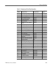
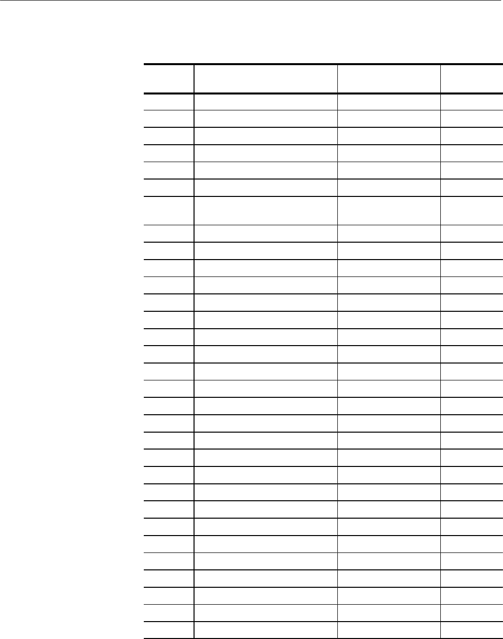
Table 3–1: Schematics and Circuit Board Assemblies
Diagram
Number
Schematic Name Assembly Name
Assembly
Number
1 Input Amplifiers A and B1 Input A1
2 Input Amplifiers B2 and B3 Input A1
3 Probe Input & DC Restorer Vectorscope & Waveform A6 & A2
4 Input & Reference Selection Waveform A2
5 Diff Amp & Video Filters Waveform A2
6 Vertical Deflection Waveform A2
7 Vertical Control Logic, Calibrator, &
Cursors
Waveform A2
8 Ref Sync Generation Waveform A2
9 Horiz & Vertical Sync Generators Waveform A2
10 Ramp Generator Waveform A2
11 Horizontal Mag & Output Amps Waveform A2
12 Horizontal Latches & DAC Waveform A2
13 Slow Sweep & Ext Horiz Input Waveform A2
14 SCH Phase Timing Waveform A2
15 SCH Sync Locked Oscillator Waveform A2
16 Master MPU Waveform A2
17 Dynamic RAM, ROM, & NOVRAM Waveform A2
18 Line Rate Controller MPU A5
19 UART & A/D MPU A5
20 Readout Eng & Read Output MPU A5
21 Interconnect MPU A5
22 MPU Annex Annex A10
23 Front Switch Panel Front Panel (Switch) A12
24 Touch Panel Touch Panel A9
25 Vector Input & Gain Vectorscope A6
26 Diff Phase/ Gain Vectorscope A6
27 Vector Timing & Blanking Vectorscope A6
28 Demodulators Vectorscope A6
29 XY Inputs & Pix Monitor Vectorscope A6
30 Vector Deflection Amps Vectorscope A6
31 Subcarrier Regenerator Oscillator A7


