Theory of Operation
3–10
1780R-Series Service Manual
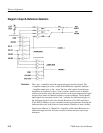
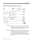
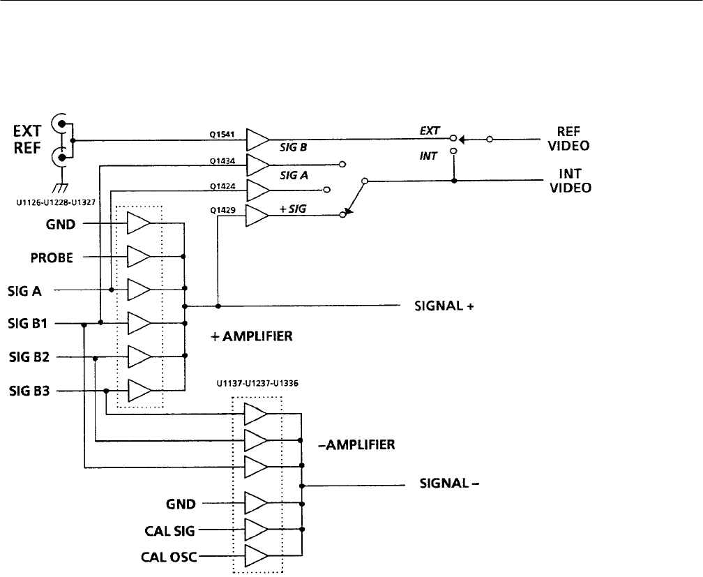
Diagram 4 Input & Reference Selection
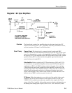
The + and – Amplifiers select the appropriate input signal for display. The
+ Amplifier output goes to the + input of the Difference Amplifier, while the
– Amplifier output goes to the – input. The four video signals from the Input
Amplifiers are connected to 6-to-1 video switches, which consist of multiple
sections of transistor arrays. Resistive networks at the inputs attenuate the signal
and provide a means for channel frequency response matching. The B channel
input signals are connected to both + and – switches for differential display of
the A-B input signals. Probe video and the Waveform (CAL SIG) and Vector
(CAL OSC) Calibrators are also switched into the signal path here. Inserting the
calibrators this early in the Vertical circuit enables calibration of more circuitry.
Signals from Channel A, Channel B, + Amplifier, and External Reference are
selected through transistor follower switches for horizontal and vectorscope
references.
Overview


