Performance Verification
4–18
1780R-Series Service Manual
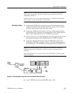
d. Connect a coaxial cable from the 1780R-Series AUX OUT connector,
through a precision (0.2%) 75 W feed-through terminator, to Ch 1 Input
on the test oscilloscope.
NOTE. The precision terminator is listed under Auxiliary Equipment. It is also
supplied with the Return Loss Bridge.
e. Check that the DC level, displayed on the test oscilloscope CRT, is
between –0.5 V and +0.5 V.
f. Move the coaxial cable from the AUX OUT connector to the PIX MON
OUT connector.
g. Check that the DC level, displayed on the test oscilloscope CRT, is
between –0.5 V and +0.5 V.
h. Disconnect the coaxial cable from the PIX MON OUT connector and the
test oscilloscope.
8. Check DC Channel Matching
Supplemental: Typically within 30 mV.
a. Check that no signal is applied to the 1780R-Series CH A INPUT
connector. Check that CH A INPUT is selected.
b. Connect a 75 W terminator to each of the following 1780R-Series
channel inputs: CH A, CH B1, CH B2, and CH B3.
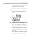
c. Connect a coaxial cable from the 1780R-Series AUX OUT connector,
through a precision (0.2%) 75 W feed-through terminator, to the +Input
connector on the test oscilloscope differential comparator.
d. Set the test oscilloscope differential amplifier controls as follows: +Input
to DC, –Input to Vc, Volts/Div to 10 mV, and BW to 5 MHz.
e. Use the test oscilloscope differential comparator Comparison Voltage
control to set the trace on the center graticule line. This is the DC
reference level.
f. Select INPUT–CH B1 on the 1780R-Series front panel.
g. Check that the trace is located within 30 mV of the DC reference level.
h. Select INPUT–CH B2.
i. Check that the trace is located within 30 mV of the DC reference level.
j. Select INPUT–CH B3.
k. Check that the trace is located within 30 mV of the DC reference level.


