Performance Verification
1780R-Series Service Manual
4–27
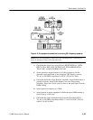
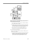
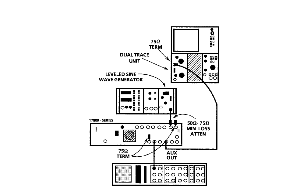
Figure 4–9: Connections for checking AUX OUT frequency response. (Only Ch 1 of
the test oscilloscope dual-trace unit is used.)
g. Set the generator to each of these frequencies: 3.58 MHz (4.43 MHz for
PAL), 5 MHz, 8 MHz, and 10 MHz.
h. Check the response for each frequency given in part g. of this step. The
amplitude displayed on the test oscilloscope CRT should be within ±2%
or ±14.3 mV for NTSC (±14.0 mV for PAL) of the amplitude noted in
part d. of this step. Take into account generator flatness error.
i. Disconnect the sine wave signal from the CH A INPUT connector.
Disconnect the test oscilloscope from the AUX OUT connector.
17. Check X1 Probe Frequency Response
Requirement: Flat frequency response from 50 kHz to 10 MHz within ±3%.
50 kHz is used as a reference.
a. Connect the leveled sine wave generator output, through a 50 W-to-75 W
minimum loss attenuator and a 75 W feed-through terminator, to the
1780R-Series front-panel PROBE input connector. Connect a 75 W
end-line termination to the rear-panel PIX MON OUT connector.


