Theory of Operation
1780R-Series Service Manual
3–35
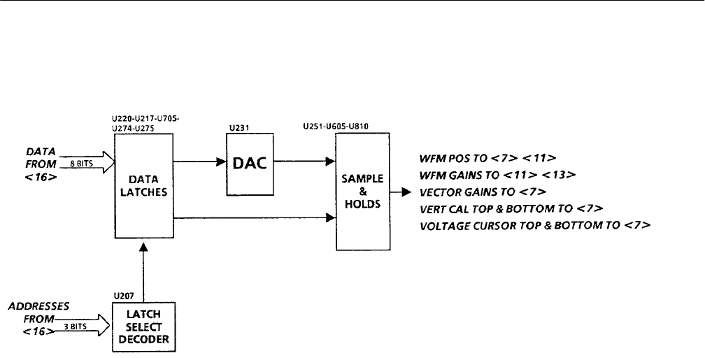
Diagram 12 Horizontal Latches & DAC
Eight-bit digital data from the Microprocessor, used to control horizontal as well
as some vertical functions, is latched onto the circuit board. A Latch Select
Decoder, using three address bits, controls the Data Latch operation. Data bits
from the latches are input to a 16-bit Digital-to-Analog-Converter (DAC) that
converts the data bits to the analog voltage levels used for gain setting and
positioning.
Latches. The five identical latches (U220, U217, U705, U274, and U275) write
data from the data bus to their outputs on the rising edge of their clock pulses.
The data is held on their outputs until new data is written on the next clock
pulse. U220 and U217 write data into the DAC. U705 controls sequencing of the
DAC output to the 11 Sample-and-Hold circuits. U274 and U275 directly output
a number of control signals, most of which are used by the horizontal and sweep
circuits.
Latch Select Decoder. The Latch Select Decoder generates the clock for the eight
latches to receive data from the data bus. When the /VH HRDW CTRL input is
pulsed low, one of the outputs (Y0 through Y7) goes low for the duration of the
pulse. When the /VH HRDW CTRL returns high, the output goes high to
generate a positive-going transition that is the clock edge for the selected latch.
DAC. The DAC, U231, has an output voltage range of ±3 volts and 16 bits of
resolution. The DAC has no internal latches and its analog output continuously
follows its digital input. R231 is the gain control for the DAC output. The DAC
output is utilized only when one of the analog switches is closed, to connect its
analog output to one of the Sample-and-Hold circuits.
Overview
Circuit Theory


