Performance Verification
1780R-Series Service Manual
4–25
a. Connect the leveled sine wave generator output, through a 50 W-to-75 W
minimum loss attenuator, to the CH B2 INPUT connector. Do not
terminate the loop-through connector.
b. Select INPUT–CH B2.
c. Check repeat step 11b. through 11p. to check the frequency response of
the 1780R-Series CH B2 INPUT. Parts b., e., and p. should read “CH B2
INPUT” when using the step 11 procedure as a guide. Also, part j.
should read ±14.3 mV for NTSC (±14.0 mV for PAL) when checking
these frequencies: 8 MHz and 10 MHz.
14. Check X1 Gain CH B3 Frequency Response
Requirement: Flat frequency response from 50 kHz to 5 MHz within 1%.
50 kHz is used as a reference. Flat frequency response from 5 MHz to 10
MHz within ±2% of the reference amplitude. 10 MHz to 15 MHz should be
within +2% and –5% of the reference amplitude. 15 MHz to 20 MHz should
be within +2% and –15% of the reference amplitude.
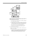
a. Connect the leveled sine wave generator output, through a 50 W-to-75 W
minimum loss attenuator, to the CH B3 INPUT connector. Do not
terminate the loop-through connector.
b. Select INPUT–CH B3.
c. Check repeat step 11b. through 11p. to check the frequency response of
the 1780R-Series CH B3 INPUT. Parts b., e., and p. should read “CH B3
INPUT” when using the step 11 procedure as a guide. Also, part j.
should read ±14.3 mV for NTSC (±14.0 mV for PAL) when checking
these frequencies: 8 MHz and 10 MHz.
d. Disconnect the termination from the PIX MON OUT connector and the
Peak-to-Peak Detector Head from CH B3 INPUT.
15. Check Auxiliary Input Frequency Response
Requirement: Flat frequency response from 50 kHz to 10 MHz within ±2%.
50 kHz is used as a reference.
a. Connect the leveled sine wave generator output, through a 50 W-to-75 W
minimum loss attenuator, to the AUX IN connector.
b. Check that the 1780R-Series front-panel controls are set for normal
1-volt peak-to-peak waveform monitoring except as follows: Select the
FILTER–AUX mode. Check that the 1780R-Series INPUT selection is
set to CH A. Check that the WAVEFORM GAIN button is set to Off (X1
Gain).


