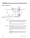
Theory of Operation
3–50
1780R-Series Service Manual
currently being used and a TaskData stack that is being built for a new line
number selection, or a different line rate, etc. The two bytes that are actually
TaskData consist of data bits that go to control lines (WLS LINE, WRO START,
etc.) for the Readout Engine and Z-Axis at specific video line numbers. The Line
Rate Controller keeps track of the actual video line number through the
synchronization signals (V SYNC, –REF H SYNC, etc.).
Processor (U167, U367). The Line Rate Controller receives its information
(TaskData) from the Master MPU Diagram 16 on the Internal Data Bus
(ID0-ID7) and control lines /RD, /WR, /LRC, and data bit IA0. It has a protocol
that consists of instructions for starting a TaskData list, loading the TaskData list,
and ending a TaskData list.
Starting the TaskData list consists of Start TaskData ID byte followed by a Port 1
(P1.0 through P1.7) configuration byte, and Ports 4 and 5 (P4.0 through P4.7 and
P5.0 through P5.7) initial state bytes.
The TaskData is sent in packets of 5 bytes each. The first byte is the TaskData ID
byte. The next two bytes specify the video line number where the task is to be
delivered. The last two bytes are data bits for the Readout and Z-Axis control
(Ports 4 and 5). If the instruction is TaskData, the 4 bytes consisting of the
TaskData and video line number are sent to the Static RAM, U475. If the
instruction is a Start List instruction, the RAM pointer is reset to zero. If the
instruction is an EndList, the loading of TaskData is complete. When TaskData is
complete, a bit is set so that at the start of a new video frame the TaskData stack
becomes the new operational stack.
Input Signals. The following signals are applied to the Line Rate Controller
(Processor U167 and U367):
–REF H SYNC (T0, INT 0) are video timing pulses that are synchronous
with incoming video. The negative edge occurs 1.5 ms after the edge of video
and is 1.2 ms wide.
–REF H SYNC is used to count and synchronize the TaskData bits. It is
applied to U367 through T0, which increments an internal counter. The
counter keeps track of the actual video line number. The –REF H SYNC also
drives the INT 0 input to interrupt the Line Rate Controller every line. When
interrupted, the Controller checks the counter number against the current line
number in the Static RAM, U475. If the counter and line number agree, the
TaskData bits are sent to the Data Latch, U165. The next –REF H SYNC
then latches the data to the output. When the data is latched out, the RAM
pointer is incremented by four to point to the next TaskData item.
–REF H SYNC (pin 3 of U167), BRUCH Frame Pulse (pin 4), FIELD 1 (pin
5), and V SYNC (pin 6) are all used to synchronize the Line Rate Controller.
In the All Fields, 2 of 4, or 4 of 8 field modes, V SYNC and –REF H SYNC
Circuit Theory


