Performance Verification
4–50
1780R-Series Service Manual
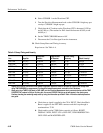
e. Set the television test signal generator Variable Sync to On. Adjust the
Variable Sync control to obtain minimum output amplitude (14 dB
reduction; i.e., <8 IRE amplitude for NTSC; <57 mV for PAL).
f. Check that the Waveform CRT display is locked.
g. Set the test signal generator Variable Sync to Off.
h. Disconnect the Black Burst signal and the five feed-through terminators
from the CH A INPUT connector.
43. Check External Sync Input
Requirement: Black Burst: –14 dB to +6 dB. Composite Sync: 0.2 V to
8.0 V peak-to-peak.
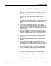
a. Connect the television test signal generator Color Bar signal, through a
75 W feed-through terminator, to the 1780R-Series CH A INPUT
connector. Check that the generator Black Burst signal is connected to
the EXT REF connector and terminated into 75 W.
b. Set the 1780R-Series control as follows: REF–EXT.
c. Unterminate the 1780R-Series EXT REF input.
d. Check that the Vectorscope and Waveform CRT displays are locked.
e. Connect five 75 W feed-through terminators to the 1780R-Series EXT
REF connector loop-through connector.
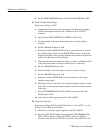
f. Set the television test signal generator Variable Sync to On. Adjust the
Variable Sync control to obtain minimum output amplitude (14 dB
reduction; i.e. <8 IRE amplitude for NTSC; <57 mV for PAL).
g. Check that only the Waveform CRT display is locked. (Ignore the
Vectorscope display.)
h. Set the test signal generator Variable Sync to Off.
i. Disconnect the five feed-through terminators from the EXT REF
connector. Connect a 75 W end-line termination to this loop-through
connector.
j. Leave the Color Bar and Black Burst signals connected to the instru-
ment.
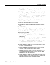
44. Check AFC and Direct Sync
Requirement: AFC Sync Lock-In Time: <1 second. Jitter With Respect to
White Noise: ≤30 ns.
Supplemental: Direct Sync Jitter: ≤12 ns.


