Theory of Operation
1780R-Series Service Manual
3–7
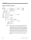
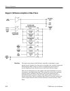
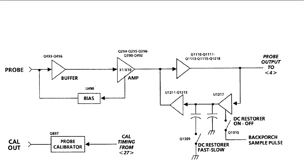
Diagram 3 Probe Input and DC Restorer
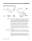
The 1780R-Series is equipped with a front-panel Probe Input, which allows it to
be used to make some measurements not normally possible with a waveform
monitor or vectorscope. The Probe Input is a high impedance input that can also
be used as another video input, when terminated with an in-line termination. The
Probe Input is configured to take either a X1 or X10 probe (Configure menu
selection) by switching in an internal 10X Amplifier when X10 is selected.
The Probe Output Amplifier has a DC Restorer identical to those used for the
video inputs. Clamping can be on the backporch or sync tip. The Probe DC
Restorer is controlled with the restorers on the four (CH A – CH B3) video
inputs; all restorers on, fast or slow, or sync tip or backporch clamp.
A front-panel Probe Calibrator Output is provided to set the probe gain and
compensation. Timing of the Probe Calibrator square wave is controlled by the
Microprocessor through the Vertical Calibrator and Filter Control in the vertical
control logic.
Probe Input Amp. The Probe Input Amplifier is a high input impedance non-in-
verting amplifier with a gain of 1.1 or 11, depending on instrument configura-
tion. Bias for the AC-coupled amplifier is provided by a low-frequency feedback
loop.
Q493 and Q496 form a high impedance, unity gain voltage follower. C495 is the
AC input coupling capacitor. CR493 and R494 provide input overvoltage
protection. C494 bypasses R494 to improve frequency response. C493 adjusts
the probe input capacitance to 20 pF. R495 and R492 set the input resistance to
1 MW.
Overview
Circuit Theory


