Performance Verification
1780R-Series Service Manual
4–61
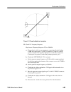
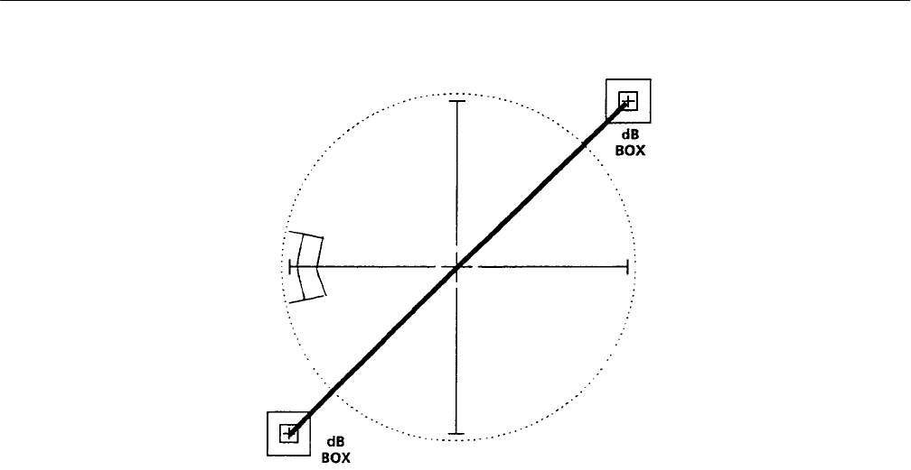
Figure 4–11: Properly adjusted xy input gains
55. Check X Y Frequency Response
Requirement: Frequency Response: DC to >500 kHz.
a. Connect the leveled sine wave generator output signal to pin 3 of the
1780R-Series rear panel X Y INPUT connector. Use the X Y INPUT
connector listed in the Auxiliary Equipment to make the connections.
Connect pin 1 to ground. Connect the generator ground to pin 1.
b. Check that LEFT DISPLAY–XY is selected.
c. Set the generator output frequency to 50 kHz and the output amplitude
for a display equal to the diameter of the compass rose on the 1780R-Se-
ries Vectorscope CRT.
d. Set the generator output frequency to 500 kHz.
e. Check that the display reaches the –3 dB gaps in the horizontal axis or
beyond. See Figure 4–10.
f. Move the generator output signal to pin 7 of the X Y INPUT connector.
Connect pin 5 to ground.
g. Check that the display reaches the –3 dB gaps in the vertical axis or
beyond.
h. Disconnect the leveled sine wave generator from the instrument.


