Adjustment Procedures
5–50
1780R-Series Service Manual
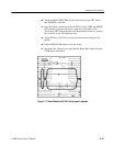
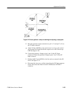
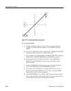
r. If necessary, move the jumper on A2J986 so the SCH dot is closest to
the burst vector reference line as displayed on the Vectorscope CRT.
(That is, close to the 0_ mark on the graticule dQ scale.)
NOTE. The jumper on A2J986 should be left at the position set by the factory.
s. Adjust Fine SCH Adj. (A2R1281)
for 0 SCH (using the 0_ mark on the
graticule dQ scale.)
t. Disconnect the TSG-170A (or TSG-271) and the feed-through terminator
from the 1780R-Series instrument. In their place, connect the television
test signal generator (1410 or 1411) Color Bar signal to the CH A
INPUT connector. Connect a coaxial cable from the other CH A INPUT
connector to the EXT REF connector. Check that the EXT REF
connector is terminated into 75 W. Check that the generator is internally
connected so that the SCH can be varied. (Refer to P339 on the 1410/
1411 generator A21 Sync Lock board.)
u. Check, by turning the generator Subcarrier Phase control (clockwise),
that the SCH dot “flips” (changes fields) between 80_ and 100_ away
from 0_ SCH. If this condition is met, go to part w. of this step. If this
condition is not met, perform part v. of this step before going to part w.
v. Readjust-Note the setting of the Ref SCH Adj (A2R1263). Readjust
A2R1263 very slightly so that the dot “flips” between 80_ and 100_.
Leave A2R1263 at this readjusted setting.
w. Leave the Color Bar signal connected to the CH A INPUT. Disconnect
the coaxial cable from the other CH A INPUT connector; terminate this
loop-through connector into 75 W. Connect Black Burst from the
generator to the EXT REF connector; check that this loop-through
connector is terminated into 75 W.
39. Adjust Timing Cursors
a. Check that the television test signal generator Color Bar signal is
connected to the CH A INPUT.
b. Select the 1780R-Series LEFT DISPLAY-VECT mode of operation.
Check that WFM HORIZONTAL-ONE-LINE mode is selected.
c. Connect the probe from a digital counter to A4TP108. Be sure to ground
the probe to the chassis.
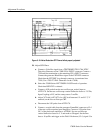
d. Adjust 10 MHz Ref (A4C109) for 10 MHz on the digital counter. A4 is
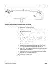
the Z-Axis board. See Figure 5–19.


