Performance Verification
4–60
1780R-Series Service Manual
h. Adjust the variable VECTOR GAIN control so that the burst vector
length reaches the 20% DG mark on the 180_ graticule line.
i. Turn the Precision Measurement control to null the burst.
j. Check that the PHASE readout on the Vectorscope CRT is between
+1.00_ and –1.00_.
k. Set the VECTOR GAIN–VAR mode to Off. Press the MEASURE button
to exit the menu.
l. Disconnect the Color Bar signal and 75 W terminator from the instru-
ment.
54. Check X and Y Input Phase Matching
Requirement: Input Phase Matching: Less than a trace width of separation at
20 kHz.
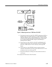
a. Connect the – Output from the sine wave oscillator to pin 1 (–X Input)
and pin 5 (–Y Input) of the X–Y Input Connector listed in the Auxiliary
Equipment. Connect the oscillator + Output to pin 3 (+X Input) and pin
7 (+Y Input) of the X–Y Input Connector.
b. Connect the X Y Input Connector to the 1780R-Series rear panel X Y
INPUT connector.
c. Select LEFT DISPLAY–XY on the 1780R-Series front panel.
d. Set the sine wave oscillator frequency to 1 kHz. Adjust the oscillator
output amplitude so the trace extends between the targets (+) on the
diagonal line as displayed on the Vectorscope CRT.
e. Set the sine wave oscillator output frequency to 20 kHz.
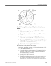
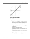
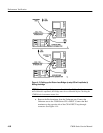
f. Check that there is less than a trace width separation along the diagonal
line. See Figure 4–11.
g. Disconnect the sine wave oscillator from the X Y Input Connector.


