Adjustment Procedures
1780R-Series Service Manual
5–13
1. Equipment Connections
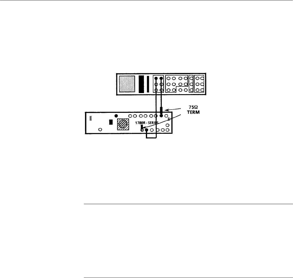
a. Connect the television test signal generator Color Bar signal, through a
75 W feed-through terminator, to the 1780R-Series CH A INPUT
connector. See Figure 5–6.
Figure 5–6: Initial signal connections for re-adjustment of the 1780R-Series
b. Connect the television test signal generator Black Burst signal to the
1780R-Series EXT REF. Terminate the remaining side of the loop-
through connector with a 75 W terminator.
NOTE. Leave the Black Burst signal connected to the EXT REF connector
throughout the entire Calibration Procedure except when stated otherwise.
Leave Color Bar signal connected to CH A INPUT for Steps 1 through 12.
Leave the internal jumpers in their factory-set positions unless directed
otherwise in this Adjustment Procedure. The factory-set jumper positions are
listed in Section 2, Installation Electrical.
Once the instrument is powered up, allow at least 20 minutes of warm-up time
before continuing.
c. Connect the power cord to the designated mains voltage. See rear panel
LINE VOLTAGE switch setting. Set the POWER switch to ON.
d. Press the CONFIGURE button to On. Set the front-panel controls and
Configure menu selection to the initial settings given in Table 5–3. Press
the CONFIGURE button to exit the menu.
e. Use the buttons and controls below each CRT to center the displays and
set their intensity for best viewing. Press the PHASE SHIFT button to
On. Use the Precision Measurement control to place the burst vector dot
on the 180° reference line for NTSC (for PAL, position the burst vector
dots to their reference marks on the graticule).
