Theory of Operation
1780R-Series Service Manual
3–67
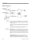
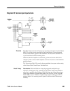
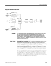
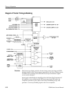
Diagram 26 Diff Phase/Gain
The Differential Gain and Phase Demodulators change a subcarrier rate signal
into DC currents proportional to chroma amplitude (gain) and phase. The
resultant current is limited (to prevent driving down-stream amplifiers into
limit), filtered (to get rid of high frequencies), and amplified to produce the
DEMOD out signal for the dP/dG Alternate Mode switch (Diagram 34) and the
Recursive Filter (Diagram 35).
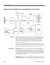
Differential Phase Demodulator. U267 is a balanced demodulator used to recover
the differential phase product. Its signal inputs are driven by chroma whose
amplitude is set by the Gain Cell on Diagram 25. The demodulator gain is set by
the value of R367, which is physically located between pins 2 and 3.
When Differential Phase Measurement is selected Q279 saturates. R273, along
with a resistor and diode internal to U267, sets the current into pin 5 at approxi-
mately 5 mA. This causes 5 mA of DC current to flow into both pins 6 and 12.
The cross-coupled, emitter-coupled output stage of the demodulator is turned on
and off by the quadrature phase signals (QFSC1 and QFSC2) from the Digital
Phase Shifter (Diagram 32). Output signal current will be alternately inverted
from the input chroma signal, at a subcarrier rate, which produces the desired
multiplication. The output currents from pins 6 and 12 drive into a current mirror
that is shared with the Differential Gain Demodulator.
Overview
Circuit Theory


