Operating Information
2–32
1780R-Series Service Manual
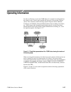
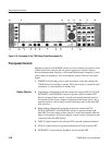
3. PARADE / OVERLAY. Momentary contact switch that cycles through
selections of sequential displays that can be up to 3 lines or 3 fields on a
single display, depending on the selected waveform sweep.
4. WFM / WFM + CAL. Momentary contact switch that cycles through
selections of standard waveform or waveform plus calibrator signal for
display on the waveform monitor CRT. Small front-panel light-emitting
diodes indicate the selected display.
5. CH A / PROBE. Momentary contact switch that selects the signal from the
rear-panel Channel A loop-through input or the front-panel Probe input for
display on both CRTs. Small front-panel light-emitting diodes indicate the
selected display.
6. CH B1 / CH B2 / CH B3. Momentary contact switch that cycles through
selections of the signal from the rear-panel Channel B1, Channel B2, or
Channel B3 loop-through input for display on both CRTs. Small front-panel
light-emitting diodes indicate the selected display.
7. A-B1 / B1-B2 / B1-B3. Momentary contact switch that cycles through the
differential input selections for display. Small front-panel light-emitting
diodes indicate the selected display. Pushing and holding this switch in
provides menu instructions for setting up new differential combinations for
this display.
8. INT / EXT / CW. Momentary contact switch that toggles between internal
(from incoming video), external (from rear-panel loop-through input) signals
for sync and subcarrier reference. Pushing and holding this switch selects the
rear-panel CW loop-through as a subcarrier reference. Small front-panel
light-emitting diodes indicate the selected reference.
9. FLAT / LUM / CHROM. Momentary contact switch that toggles through
Flat (unfiltered video signal), Luminance (chrominance filtered out), and
Chrominance (luminance filtered out) video signal for display. Small
front-panel light-emitting diodes indicate the selected filter.
Pushing and holding this button selects a multiple filter display. In 2-line or
2-field sweeps the first half of the waveform monitor display will be flat and
the second half will be the luminance filter. In 3-line or 3-field sweep the
order is flat, luminance filter, and chrominance filter. If the button is held in
during 1-line or 1-field sweep the filter reverts to flat.
10. AUX / LPASS / DIFF. Momentary contact switch that toggles through Aux
Video Input (signal is input following the video filters), low-pass filter
(300 kHz bandwidth) and the Differentiated step (rising and falling
Right Display
Input
REF
Filter


