Theory of Operation
1780R-Series Service Manual
3–85
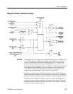
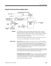
In addition, the divided by 7200 F
SC
’ produces the counter load pulse for a
Programmable Divide by 7200 Counter that outputs the reference phase to the
Phase Detector in the output phase-lock loop.
The output phase-lock loop mixes the F
SC
’ signal with the output of a second
VCXO to produce a difference signal that is low-pass filtered and converted to
TTL levels by a balanced comparator. The TTL output of the balanced compara-
tor is one input to the Phase Detector. The reference input to the Phase Detector
is the output of the programmable counter. Phase Detector output drives an
Integrating Error Amplifier, whose output is the control voltage for the 4F
SC
VCXO. The output of the VCXO is divided down to produce the IF
SC
and QF
SC
signals for the Vectorscope Demodulators. The IF
SC
signal is also fed back to the
Mixer to close the output phase-lock loop.
Mixer, Low-pass Filter, Error Amplifier, and Phase Detector. U266A and B are
Exclusive OR gates configured as a balanced mixer, where the input subcarrier
reference and the intermediate subcarrier reference (F
SC
’) are mixed to derive a
difference signal (about 500 Hz below F
SC
). Mixer output is low-pass filtered
and drives a comparator stage (U263B) configured as a Hysteresis Amplifier that
outputs a TTL error signal, of approximately 500 Hz, to drive the reference input
of the Phase Detector, U345A, a TTL frequency/phase detector.
The remaining input to the Phase Detector is the Voltage-Controlled Crystal
Oscillator (VCXO) generated intermediate subcarrier (F
SC
’). Phase difference
between the reference (R) and feedback (V) inputs of the Phase Detector directly
control the output voltage.
Error Amplifier, 4F
SC
VCXO and ÷4 Counter. The output voltage of the Phase
Detector drives U349A, an Integrating Error Amplifier, whose output is the
control voltage to the Varactor-controlled 4F
SC
VCXO.
Q155 is an oscillator stage running at approximately 4F
SC
– 2 kHz. L153 in the
tank circuit of the oscillator allows it to be tuned approximately 2 kHz low, when
the crystal frequency is 4F
SC
. U161 is a dual D-type, edge-triggered, TTL
flip-flop clocked by the output of the crystal oscillator. The /Q output of U161A
drives one input of the balanced mixer to close the phase-lock loop. In addition,
this F
SC
’ signal clocks both the ÷7200 and programmable counters, and provides
one input to the output F
SC
Mixer (U256A and B).
÷7200 and Programmable Counters. Both counters are made up of two 8-bit,
binary counters (with input registers) in cascade configuration. Both counters are
clocked by the intermediate subcarrier (F
SC
’). The ÷7200 counter register is
loaded to a fixed starting count by hard wiring inputs either high or low. The
starting count is loaded into the counter by the falling edge of the U161B Q
output. Clock enable for the second counter is the ripple carry out (RCO) of
Circuit Theory


