Installation
1780R-Series Service Manual
2–3
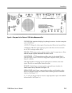
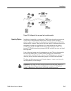
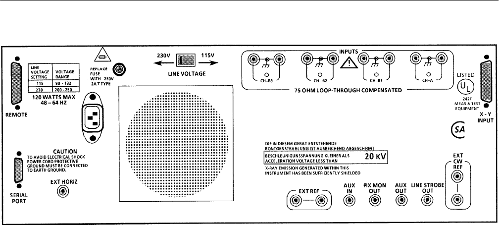
Figure 2–1: Rear panel for the Tektronix 1780R-Series Measurement Set
EXT REF. High impedance bridging loop through connector for either composite
sync or black burst.
AUX IN. 75 W input for video signals. Insertion point follows the internal filters.
AUX OUT. 75 W video signal output just prior to the filters. Can be used with
the AUX IN to design custom filters.
PIX MON. 75 W output to drive a picture monitor, signal is output prior to filters
and has a bright-up pulse added when line select is used.
LINE STROBE. A 75 W output that provides a pulse for the selected line(s)
when line select is used. Can also be configured to output the Field 1 pulse, see
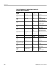
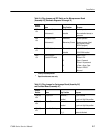
Table 2–3 (J1103).
CW. High impedance bridging loop-through input for continuous subcarrier
signal. Provides an external phase reference signal.
REMOTE. 15-pin D-type connector used as a ground closure interface for
remote control of key functions. See Figure 2–4.
SERIAL PORT. 9-pin D-type connector that provides a serial interface, using
RS422A or RS232D control, for remote control of Microprocessor-controlled
functions. See Figure 2–5.
X – Y. A 15-pin D-type connector used as a high impedance input for the 600 W
balanced audio. See Figure 2–6.


