Performance Verification
1780R-Series Service Manual
4–3
Table 4–1: Recommended Equipment (Cont.)
Electrical Instrument ExamplePerformance Requirements
9. Video Amplitude Calibration Fixture Signal; adjustable square wave 0.0 to
999.9 mV p-p with a resolution of 0.1 mV
and an accuracy of 0.05%, frequency
approximately 270 Hz.
TEKTRONIX 067-0916-00 used in a
TEKTRONIX TM500 Series Power
Module.
10. Sine Wave Generator Signal: 10 Hz to 100 kHz sine waves; –
and + balanced outputs.
A TEKTRONIX SG505 Option 02
Oscillator installed in a TEKTRONIX
TM500 Series Power Module.
11. Function Generator Signal: 1 kHz, +10 V, square waves for
checking YRGB mode of operation.
TEKTRONIX FG501A Function Genera-
tor installed in a TEKTRONIX TM500
Series Power Module.
12. Power Module Mainframe
(required for Items 4, 5, 6, 8, 9, 10, and 11)
For powering and housing TEKTRONIX
DC503A, DM503A, DM501A, FG501A,
SG503, SG505, 067-0916-00, and
015-0408-00.
For example: TEKTRONIX TM506 Power
Module Mainframe.
13. Variable Autotransformer General Radio Metered Autotransformer
W10MT3W. If 220 V operation must be
checked, a conversion transformer or
appropriate 220 V autotransformer is
needed.
14. Vectorscope Required to check differential gain and
phase of the 1780R-Series AUX OUT and
PIX MON OUT connectors. See Step 28.
Use another TEKTRONIX 1780R-Series
instrument or use a TEKTRONIX
520A-Series Vectorscope.
Auxiliary Equipment
15. Return Loss Bridge Range: At least 46 dB return loss
sensitivity, 50 kHz to 6 MHz. (Supplied
with two precision [0.2%] 75 W feed-
through terminators; Tektronix Part No.
011-0103-00 and 011-0103-01.)
TEKTRONIX 015-0149-00.
16. 75 W Terminators Seven required, at least five must be a
feed-through type.
75 W End-line Terminator (Tektronix Part
No. 011-0102-00).
Precision (0.2%) 75 W Feed-through
Terminator (Tektronix Part No.
011-0103-02).
17. 75 W Coaxial Cables Three 42 inch cables, with BNC connec-
tors are required.
RG 59U (Tektronix Part No. 012-0159-00)
18. Dual Input Coupler Matched BNC cable-T for checking
common-mode rejection. Length of arms
matched to within ±0.1 in.
Tektronix Part No. 067-0525-02.
19. 75 W 10X Attenuator Tektronix Part No. 011-0061-00.
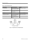
20. 5% Signal Attenuator For checking differential gain. Attenuator
accuracy: 5%, 1% of 5% (4.95% to
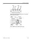
5.05%). Construct as shown in Figure
4–1.
Accessory housing, equipped with BNC
connectors but without internal electrical
components, is available by ordering as
follows: Accessory Housing, Tektronix
Part No. 011-0081-00.


