Performance Verification
1780R-Series Service Manual
4–55
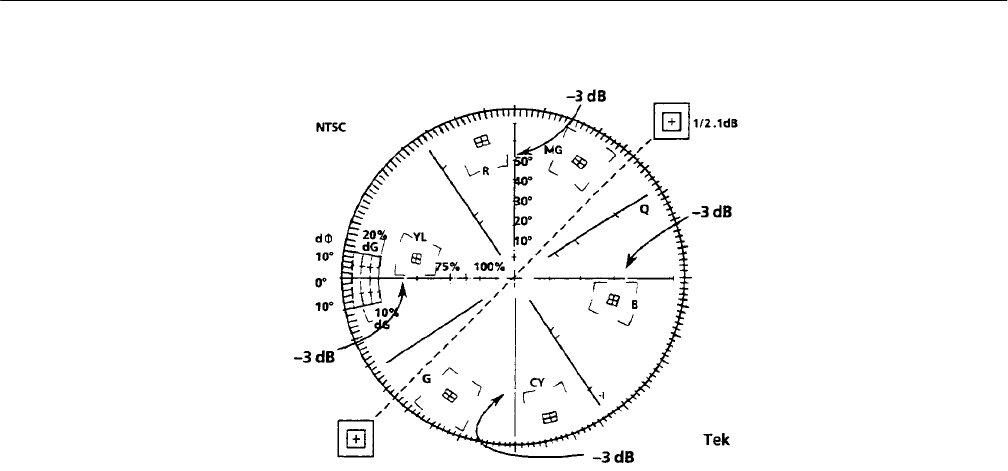
Figure 4–10: Vector graticule showing the –3 dB points for checking frequency
response
f. Set the generator output frequency to 2.979545 MHz for NTSC
(3.833619 MHz for PAL).
g. Check that the circle displayed on the Vectorscope CRT is smaller than
the 3 dB marks.
h. Set the generator output frequency to 3.979545 MHz and then to
4.179545 MHz. (Use 4.833619 MHz and 5.033619 MHz for PAL.)
i. Check that, at 3.979545 MHz, the circle is larger than the 3 dB marks; at
4.179545 MHz, the circle should be smaller than the 3 dB marks. (Use
4.833619 MHz and 5.033619 MHz for PAL.)
j. Disconnect the sine wave signal from the instrument.
49. Check Vector Display Phase and Gain Accuracy
Requirement: Vector Phase Accuracy: ±1.25. Vector Gain Accuracy: ±2.5%
(1.25 IRE). Quadrature Phasing: ±0.5_.
a. Connect the television test signal generator 75% Amplitude Color Bar
signal to the 1780R-Series CH A INPUT connector. Check that this
loop-through connector is terminated.
b. Press the PHASE SHIFT button to On.
c. Turn the Precision Measurement control so that burst is located on the
180_ graticule line as displayed on the Vectorscope CRT. (For PAL,
position the burst vector dots to their reference marks on the graticule.)
