Adjustment Procedures
1780R-Series Service Manual
5–25
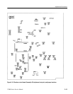
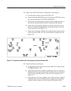
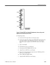
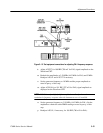
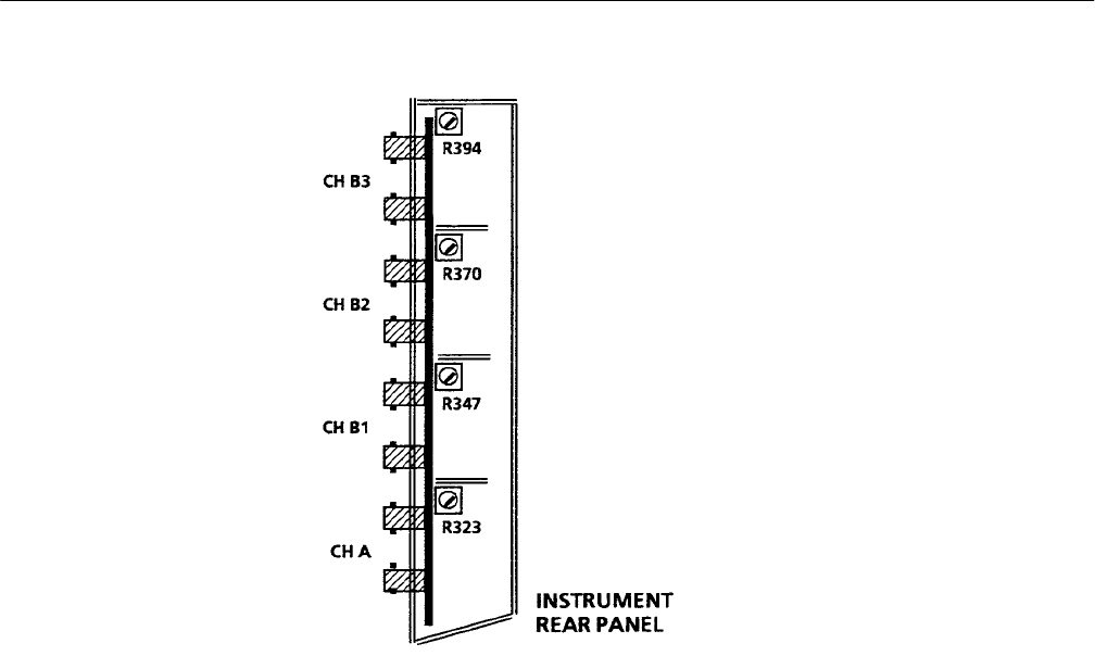
Figure 5–13: Input & BNC circuit board (A8) adjustments, shown as they would
appear with the instrument on its left side
17. Match Input Gains
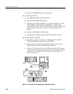
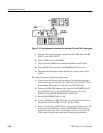
a. Connect the VAC output cable to a dual input coupler.
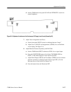
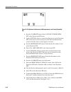
b. Connect one side of the coupler to the CH B1 INPUT and the other side
to the CH A INPUT of the 1780R-Series instrument. Check that the
Black Burst signal is applied to the EXT REF connector. See Figure
5–14.
c. Select A-B1 INPUT.
d. Check that the VAC is set to 999.9 mV.
e. Check that the WAVEFORM GAIN-X5 is On.
f. Adjust Gain A (A8R323) for a null display.
g. Move the side of the dual input coupler from the 1780R-Series CH A
INPUT to the CH B2 INPUT.
h. Select 1780R-Series B1B2 INPUT.
i. Adjust Gain B2 (A8R370) for a null display.


