Theory of Operation
3–22
1780R-Series Service Manual
R1156 and R1253 setting the AC gain. CR1155, CR1254, U1159A, and C1254
form the feedback clamp. The clamp sets sync tip to +3 V at the operational
amplifier output (U1159 pin 1). U1159B and R1260 provide a constant current
discharge path for C1254 during sync time. The clamp voltage is varied by
adjusting the current flow through CR1254. U1159C amplifies and inverts the
separated sync producing a 5 volt, negative-going sync pulse at its collector (pin
14).
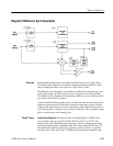
Reference Sync Separator. The selected reference video is input through a
1.5 MHz active low-pass filter made up of Q1475, Q1374, and associated
components. The filtered video drives U1483, a monolithic Sync Separator.
Negative-going composite sync is output on pin 5, which is an open collector
output allowing R1378 and CR1273 to pull-up and clamp the signal for a 0 to
+5.3 V output swing. When J1483 is set to the sound-in-sync (SIS) position,
U1483 replaces the sync time with a fixed, 5 s pulse. This provides proper
synchronization even if digital data such as sound-in-sync is present during
horizontal sync time.
Filtered Reference Video is inverted and scaled so that sync-to-blanking is
800 mV, and then is output as AGC video on pin 13. Q1380 buffers the signal
and outputs it to the Slow Sweep Triggering (Diagram 13). Q1483, R1480, and
R1481 limit the Sync Separator AGC range so that it does not output noise
bursts with no input video.
Sync Locked Oscillator. The Sync Locked Oscillator is locked to sync by a PLL
(Phase Locked Loop). U1060 is the phase detector/error amplifier which
compares the phase of the VCXO, U1065C, to one-shot U1270A’s output. The
140 ns pulse (100 ns for PAL) at the output of U1270A is box-car delayed. by
U1270B to provide a calibration adjustment, R1263, for the external reference
sync phase. (Box-car delay is accomplished by using two one-shots; one is
triggered and the other provides delay.) C1072 is adjusted to center the VCXO
(Voltage-Controlled Crystal Oscillator) operating point.
Reference Sync Phase. The Sync Locked Oscillator output is input to one port of
a Mixer, U1277. The Reference Video is multiplied by 2 by an inverting
amplifier (Q1471 and Q1472), filtered by a chroma bandpass filter (C1370 and
L1374), and input to the second port of the Mixer. The Mixer, U1277, is turned
on at burst time by saturated switch Q1389 that is keyed by the Burst Gate
output of the Sync Separator (U1483 pin 4). A differential current is output,
during burst time, from U1277 (pins 6 and 12). Its magnitude is determined by
the phase difference between the Reference Video burst and the output of the
Sync Locked Oscillator. This differential current flows in R1176, R1177, and
C1179 where it is filtered and converted to a voltage to drive a comparator,
U1179. The REF SCH ADJ (R1263 in the Sync Locked Oscillator) adjusts the
start time of the Sync Locked Oscillator so that the comparator outputs a positive


