Theory of Operation
3–58
1780R-Series Service Manual
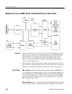
State Machine Latch. The 4-bit output of the Data Latch is input to the State
Machine Latch (U171, U376, and U385). In addition to the outputs from the
Data Latch, control signals from the Line Rate Controller are latched by the State
Machine Latch at a 500 kHz rate to control the Readout State Machine.
Readout Multiplexer. U170 is an up/down counter that is load enabled by its own
BO (Borrow Out) output forming a divide-by-7 counter that is clocked by the -H
Ref sync pulse. Pin 6 (QC output) selects readout for four horizontal lines and
waveform for three horizontal lines.
Readout State Machine. The Readout State Machine consists of five PALs (U175,
U177, U180, U185, and U187). The first portion of the state machine cycle pulls
HOLD/ low to force the Master MPU to relinquish control of the Internal Data
(ID) Bus (within 2 ms). When the Master MPU relinquishes control, the DRAM
Controller (Diagram 17) asserts /ROEN in order to output a readout address on
internal address lines IA2..IA12. The address must be active and stable no later
than 75 ns after the falling edge of /ROEN or an error will result. The four
highest address (IA14 through 17) are set high at the input of Line Driver U485.
Once the addresses are received the DRAM Controller enables two read cycles
with suitable timing for the DACs, U470 and U487. The first word of data is
latched on the rising edge of LATCH1, with the second word latched on the
rising edge of LATCH2. /ROEN is removed at this time and no further addresses
are put on the Internal Address Bus.
The Readout State Machine ends the cycle by setting /HOLD high immediately
after the rising edge of LATCH2.
DACs. U470 and U487 are 12-bit Digital-to-Analog Converters that are loaded
from the Internal Data (ID) Bus; the 4 MSBs are not used. The Load (/LDC) is
from the state machine. Write enables (WR) are provided by the /LATCH signals
from the Line Rate Controller. /LATCH1 write enables the horizontal DAC,
U470, and /LATCH2 enables the vertical DAC, U480. The analog outputs drive
sample-and-hold circuits, U560A and U565.
Address Counter – Line Driver. The Address Counter (U487) starts when the
increment from U185 goes low. It is reset when the clear from U185 goes high.
The count is input to the Line Driver (U480 and U485) to output an address on
the Internal Address Bus when the DRAM Controller sets /ROEN low.
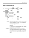
Sample-and-Holds. U560A and U565 form the Vertical Sample-and-Hold circuit.
U560A is connected to compare the output signal to the DAC output. Its gain is
unity, with the output driving the sample-and-hold (U565) input. The input
signal is sampled and the level stored on the Hold capacitor (C465) on the rising


