Adjustment Procedures
1780R-Series Service Manual
5–21
11. Adjust Vector CRT Trace Rotation, Orthogonality, and Geometry
a. Press the button under the Vectorscope CRT to On.
b. Touch the TRACE ROTATION pad on the Waveform CRT. Be sure that
the circle surrounds the words TRACE ROTATION.
c. Turn the Precision Measurement Control to align the horizontal lines of
the electronic graticule parallel with the Vectorscope CRT graticule.
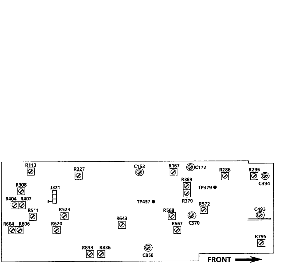
d. Adjust Vector Orthogonality (A6R511) so that the vertical lines of the
electronic graticule are perpendicular to the horizontal lines. (A6 is the
Vectorscope board.) See Figure 5–11.
e. Adjust Vector Geometry (A3R101) for straight electronic graticule lines
on the Vectorscope CRT. (A3 is the Vectorscope HV Supply board. See
Figure 5–8.)
Figure 5–11: Adjustment locations on the Vectorscope circuit board (Assembly A6)
12. Align Vector Electronic Graticule
a. Check that the button below the Vectorscope CRT is On. Check that the
CALIBRATE button is On.
b. Adjust Readout Horiz Pos (A6R523) and Readout Vert Pos (A6R620) so
that the center of the electronic graticule coincides with the exact center
of the Vectorscope CRT graticule. (A6 is the Vectorscope board. See
Figure 5–11.)
c. Adjust Readout Horiz Gain (A6R836) and Vert Readout Gain (A6R833)
so that the outer vertical and horizontal lines of the electronic graticule
coincide with the compass rose (Vectorscope CRT graticule circle).
