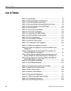
Table of Contents
vi
1780R-Series Service Manual
Figure 4–1: 5% signal Attenuator for checking differential gain 4–4. . . .
Figure 4–2: Rear view of the X Y plug connections. (Pins 2, 4, 6,
10, 12, and 14 can be used to make ground connections.) 4–5. . . . . . .
Figure 4–3: REMOTE connector modified for Remote Sync input 4–5. .
Figure 4–4: RGB Parade Display Test Connector 4–6. . . . . . . . . . . . . . . .
Figure 4–5: Initial equipment hook-up for the Performance Check
Procedure 4–11. . . . . . . . . . . . . . . . . . . . . . . . . . . . . . . . . . . . . . . . . . . . . .
Figure 4–6: Test equipment connections for checking calibrator
amplitude accuracy 4–13. . . . . . . . . . . . . . . . . . . . . . . . . . . . . . . . . . . . . .
Figure 4–7: Identification of marks and divisions on the graticule
baseline 4–16. . . . . . . . . . . . . . . . . . . . . . . . . . . . . . . . . . . . . . . . . . . . . . . .
Figure 4–8: Test equipment connections for checking CH A
frequency response 4–23. . . . . . . . . . . . . . . . . . . . . . . . . . . . . . . . . . . . . .
Figure 4–9: Connections for checking AUX OUT frequency response.
(Only Ch 1 of the test oscilloscope dual-trace unit is used.) 4–27. . . . .
Figure 4–10: Vector graticule showing the –3 dB points for checking
frequency response 4–55. . . . . . . . . . . . . . . . . . . . . . . . . . . . . . . . . . . . . .
Figure 4–11: Properly adjusted xy input gains 4–61. . . . . . . . . . . . . . . . . . .
Figure 4–12: Connections for checking line strobe pulse timing 4–63. . . .
Figure 4–13: Setting up the Return Loss Bridge: a) setup 500 mV
amplitude; b) Nulling the bridge 4–66. . . . . . . . . . . . . . . . . . . . . . . . . . .
Figure 4–14: Measuring return loss of 1780R-Series CH A INPUT 4–67. .
Figure 5–1: Simplified representation of the 1780R-Series Video
Measurement Set, showing the location of the four control
groups 5–2. . . . . . . . . . . . . . . . . . . . . . . . . . . . . . . . . . . . . . . . . . . . . . . . .
Figure 5–2: Calibrate menu as displayed on the Vectorscope CRT 5–2. .
Figure 5–3: 1780R-Series circuit board assembly locations 5–3. . . . . . . .
Figure 5–4: Rear view of the X Y plug connections. (Pins 2, 4, 6,
10, 12, and 14 can be used to make ground connections.) 5–7. . . . . . .
Figure 5–5: RGB Parade Display Test Connector 5–7. . . . . . . . . . . . . . . .
Figure 5–6: Initial signal connections for re-adjustment of the
1780R-Series 5–13. . . . . . . . . . . . . . . . . . . . . . . . . . . . . . . . . . . . . . . . . . .
Figure 5–7: Adjustment and test point locations on the
Waveform HV Supply circuit board (Assembly 16.) 5–15. . . . . . . . . . .
Figure 5–8: Adjustment locations on the Vectorscope HV Supply
circuit board (Assembly A3) 5–17. . . . . . . . . . . . . . . . . . . . . . . . . . . . . .
Figure 5–9: Adjustment locations on the Microprocessor circuit
board (Assembly A5) 5–18. . . . . . . . . . . . . . . . . . . . . . . . . . . . . . . . . . . .
Figure 5–10: Waveform circuit board (Assembly A2) adjustment,
test point, and jumper locations. 5–19. . . . . . . . . . . . . . . . . . . . . . . . . . .


