Troubleshooting Procedures
1780R-Series Service Manual
6–25
13. Set the Variac to 40 V. Adjust the external DC supply for 18 V.
14. Use the test oscilloscope to check the waveform on the base of Q460 has
approximately 20% duty cycle and a period of about 4 ms.
15. Connect the test oscilloscope probe to the anode of CR140 and check for an
approximate 150 V signal; voltage snubber working.
16. Move the probe to the collector of Q250 and check for a waveform.
17. Remove the short across VR570, the shorting strap from U360 pin 3, and the
external power supply leads.
At this point the power plug J600 can be reconnected or all supplies can be
externally loaded. However, if the power supply fails to operate the instrument, it
will be necessary to attempt to operate with an external load to determine if the
problem is with the power supply or in the load (instrument circuits).
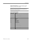
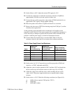
18. Connect either the external load or reconnect J600. Table 6–4 has the
resistance values for the loads. Do not remove the isolation transformer.
Table 6–4: Power Supply External Load Resistances
Supply
Resistance for
13 W Load
(for troubleshooting)
Resistance for
80 W Load (simulated
instrument load)
J600 pin connections
for power supply loads
Gnd. 31 – 39
+5 V 5 W 5W 1.7 W 15W 41 – 50
+15 V 100 W 3W 11 W 20W 17 – 22
–15 V 100 W 3W 11 W 20W 11 – 16
+60 V 1 kW 4W 144 W 25W 5 – 8
19. Set the variac for 110 V. Connect the test oscilloscope probe to W401 and
check for ≈+5 VDC, adjustable with R219.
20. Adjust the variac for mains potential of 90 V and then 130 V and check that
the test oscilloscope still reads the same as it did in step 19 (≈+5 VDC).
21. Adjust the voltage down with the variac, while watching the test oscillo-
scope. At 80 V the power supply should cease to operate (under voltage
lockout).
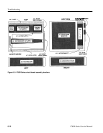
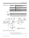
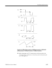
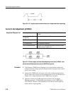
22. Set the variac to 110 V. Check the following waveforms (see Figure 6–8):
A. Q250 collector requires X100 probe (≈750 V)
B. Q250 base
C. Q350 Q451 emitter


