Adjustment Procedures
5–26
1780R-Series Service Manual
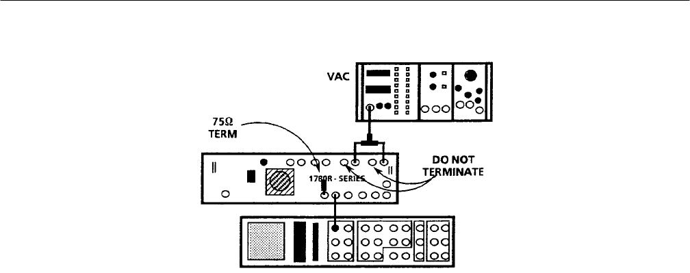
Figure 5–14: Test equipment connections for matching CH A and CH B1 input gains.
j. Move the side of the dual input coupler from the 1780R-Series CH B2
INPUT to the CH B3 INPUT.
k. Select 1780R-Series B1-B3 INPUT.
l. Adjust Gain B3 (A8R394) for minimum amplitude or null display.
m. Select INPUT-CH A and set the WAVEFORM GAIN-X5 to Off.
n. Disconnect the dual input coupler and the VAC signal from the CH A
INPUT.
18. Adjust Waveform Variable Gain Registration
a. Connect the television test signal generator Color Bar signal through a
75 W feed-through terminator to the 1780R-Series CH A INPUT. Check
that the Black Burst signal is connected to the EXT REF input.
b. Press the CONFIGURE button to On. Select DC-RESTORER-SLOW
and COUPLING-AC. Set the CONFIGURE button to Off. Select
INPUT-CH A and WFM HORIZONTAL-ONE-LINE.
c. Set the WAVEFORM GAIN to VAR.
d. Use the 1780R-Series VERT POS control to position the back porch to
the graticule baseline (0 IRE for NTSC; 0.3 V for PAL).
e. Adjust Var Gain Regis (A2R510) for no backporch or blanking level DC
position movement while the variable WAVEFORM GAIN control is
rotated full range. Once that no movement is achieved, turn the VERT
POS control to reposition the back porch to the graticule baseline.
