Theory of Operation
3–26
1780R-Series Service Manual
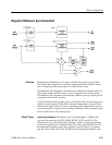
Ref H Sync Generator. The Reference Horizontal Sync Generator is made up of
two one-shot multivibrators. U596B is triggered by the direct or AFC sync from
the Direct or AFC switch. Its Q output is a 0.5 ms pulse whose trailing edge
triggers the second one-shot. Using the trailing edge of the first one-shot output
provides a 0.5 ms delay to the leading edge of Ref H Sync. The Ref H Sync has a
period of 1.2 ms and is output as –Ref H Sync from the /Q output and + Ref H
Sync from the Q output.
Internal Sync Detector. U767A is a non-retriggerable one-shot multivibrator,
triggered by the negative-going internal sync. It has a period of 51 ms, which
prevents it from being triggered by vertical equalizing pulses, but enough short
of the H sync rate to allow for normal H-rate trigger. When internal sync is
present the Q output is high most of the time, which charges C771 and keeps
U767B from being triggered. U790A is an OR gate that is driven by the Q
outputs of either U767A or B. When Q767A is being triggered, U767B is
disabled and U790A outputs the Q output from U767A.
If there is loss of internal sync, U767A is not triggered and the charge on C771
decays and allows U767B to be triggered by the output of the Direct or AFC
Sync switch. When this condition occurs the output of U790A is the Q output
from U767B.
The outputs from U790A and U395 (Direct or AFC switch), through J865 and
J866, are used to drive the Waveform and Vector Clamp Generators. Driving
U790A with either the internal sync triggered output of U767A or the reference
sync output of the Direct or AFC switch output of U767B ensures a clamp
timing pulse at all times.
FLD 1/FLD 2 Switch. The switch output, Fld Retrace Gate, controls when the
vertical sweep starts in the 2-field sweep mode. In 2-field sweep mode, the
Configure menu provides a choice of triggering on monochrome field 1 (color
field 1 or 3) or field 2 (color field 2 or 4). In 1-field or 3-field sweep the Field
Sweep Gate (Diagram 10) outputs a triggering signal for each V sync pulse.
U395 controlled by the Fld2/Fld1 and 2L/F control lines selects either the Q or
/Q output of U297B and inverts it for input to the Field Sweep Gate. Because the
output of U297B is about a half line long, selecting one or the other of its
outputs provides a high on the Fld Retrace Gate for either the first or last half of
the line.
When the Fld2/Fld1 line is high, for NTSC signals (monochrome field 2
selected), U395 selects the Q output of U297B, inverts it and outputs a high Fld
Retrace Gate during the first half line. When the Fld Retrace Gate is high on the
first half of the line it corresponds to the V sync for color fields 2 or 4 and the
field rate sweep is triggered on field 2. When Fld2/Fld1 goes low, U395 selects
the Q output of U297B, which is inverted to provide a high for the second half of
the field to correspond with field 1. Because the period of the /Q or Q output is


