Installation
1780R-Series Service Manual
2–7
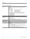
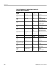
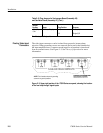
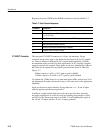
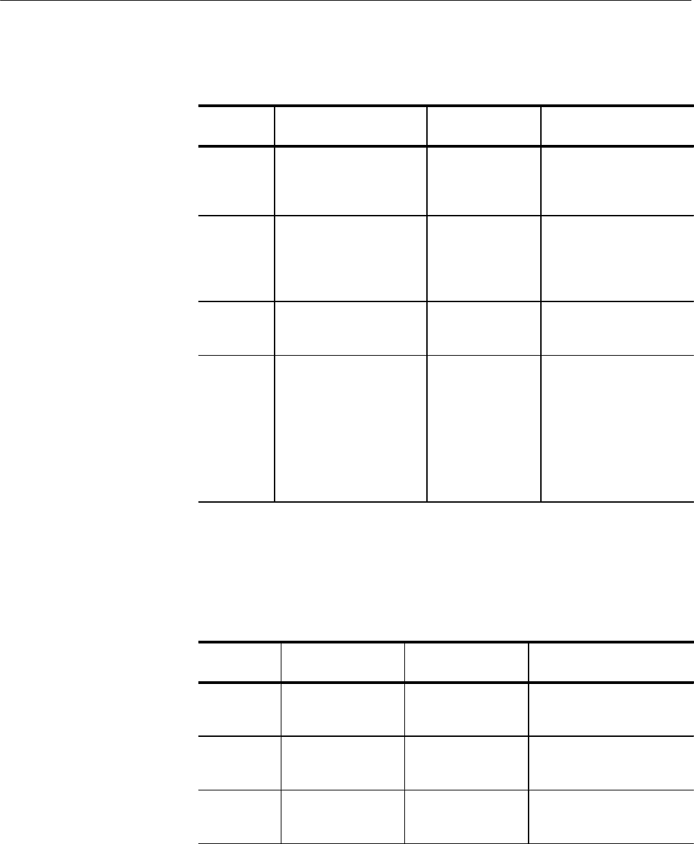
Table 2–4: Plug Jumpers and DIP Switch on the Microprocessor Board
(Assembly A5) (Schematic Diagrams 16 through 19)
Jumper
Number
Name Plug Position Purpose
J342
<16>
mProcessor Restart
Maintenance }
Removed {
Installed
Normal operation
Non-maskable interrupt to
processor
J344
<16>
mProcessor Reset
Maintenance }
Removed {
Momentary Closure
Normal operation
Resets processor (Used
with a factory startup
DEBUG program)
J453
<17>
RAM Part Selection Removed {
Installed
128 K RAM installed
512 K RAM installed
S385
<19>
Special purpose
4-position DIP switch
1
2
3
4
Open = NTSC
Closed = PAL
Open = Password
Closed = No password
} Open = Norm. Oper.
Closed = DEBUG
Not used.
{
Factory installed position.
}
Special maintenance use only.
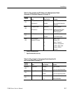
Table 2–5: Plug Jumpers for Vectorscope Board (Assembly A6)
and Oscillator Board (Assembly A7)
Jumper
Number
Name Plug Position Purpose
J108 (A6)
<29>
X Input Gain Removed {
Installed
X gain is normal
X gain is in High Gain position
J205 (A6)
<29>
Y Input Gain Removed {
Installed
Y gain is normal
Y gain is in High Gain position
J321 (A6)
<27>
Center Dot Blanking 1-2
2-3_ {
Center dot unblanked
Center dot blanked


