Corrective Maintenance
6–14
1780R-Series Service Manual
7. To re-assemble, reverse the procedure.
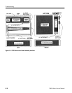
Use the following procedure to remove the Oscillator board.
1. Unsolder the ground and center conductor wires from the EXT CW REF
rear-panel BNC connector.
2. Unplug the coaxial cable connector from J499 on the Oscillator board (A7).
3. Remove two screws that hold the lower (tabs) edges of the board to the
chassis.
4. Disconnect the ribbon cable connector from J115 on the board.
5. Remove the four screws that hold the upper edge of the board to the chassis.
6. Lift the board out of the instrument.
7. To re-assemble, reverse the procedure.
Use the following procedure to remove the Z-Axis board.
1. Remove the two screws from the lower (tabs) edges of the board.
2. Disconnect the ribbon cable from J302 on the Interconnect board (A11).
3. Disconnect the ribbon cable from J180 on the Z-Axis board (A4); also
disconnect the three-wire connector from J156 on this same board.
4. Remove the four screws that hold the upper edge of the board to the chassis.
5. Lift the board out of the instrument.
6. To re-assemble, reverse the procedure.
Removing the Oscillator
Board
Removing the Z-Axis
Board


