Theory of Operation
3–90
1780R-Series Service Manual
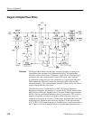
Diff Gain/Phase Alternate Mode Switch. U425 implements a Switchable Polarity
Amplifier, which outputs a differential current. Pin 4 is the signal input;
transconductance gain is set by R422. The pin 6 output drives the + input of a
Differential Operational Amplifier and pin 12 drives the – input. Levels at pin 8
and pin 10 dictate the polarity of the output from the Differential Amplifier.
When pin 10 is high, there is no inversion between the pin 4 input and the Alt
Demod signal. If pin 8 is high, the Alt Demod output is inverted. The gain is
unity between pin 4 and the Alt Demod signal, which goes back to the Waveform
Monitor Diff Amp and Video Filters (Diagram 5).
DAC. An Offset DAC, U325, provides a variable level for dG measurements
(from measurements knob setting, through the Microprocessor). For dP
measurements the DAC outputs a fixed level, corresponding to center range.
DAC current output is converted to a voltage by U221A and B (operational
amplifiers). R322 calibrates the gain to ensure that 750 mV is equal to 7% or 7_
(5% or 5_ PAL). R315 sets the DC level to center the DAC in its range and
compensate for the DC level out of the demodulator.
Data Latch. U330 is an octal, D-type flip-flop that latches data from the Micro-
processor Data Bus. All communication from the Processor to the Oscillator and
Recursive Filter circuit boards is through this latch. U243 is a TTL 3- to 8-line
decoder/de-multiplexer used to decode the memory mapped Oscillator circuit
board addresses. Clock signal for the Data Latch is from the Y3 output of U243.


