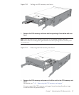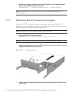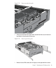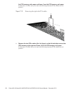
Note -
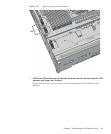
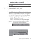
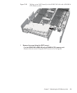
Mount the memory in the same position as it was mounted in the removed CPU
memory unit upper.
Note -
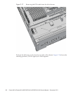
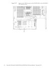
A part of the procedure varies depending on the CPU memory unit type. To
determine the CPU memory unit type, check the label in Figure 7-2.
11.
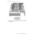
Remove th e memory m od ules from the removed CPU memory unit upp er and
then install th em in the new CPU m emory unit upper.
For details, see "8.5 Removing Memory"and"8.6 Installing Memory."
7.4.4 Removing a PCI Express cable
When reducing a CPU memory unit upper or when replacing a PCIe cable, remove
the PCIe cable. You can expand a CPU memory unit upper by performing the above
procedure up to step 9.
For the SPARC M10-4 with a FRAME-A CPU memory unit and the SPARC M10-4S
with a FRAME-B CPU memory unit, perform the procedure from step 2.
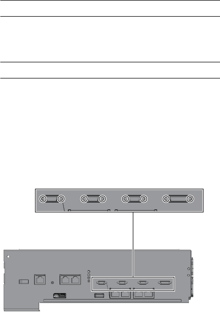
1.
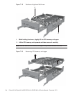
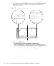
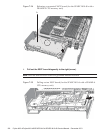
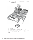
Remove th e eight scre w s at both ends o f the XS CF cable connection port on
the r e ar of the CPU m emory unit low er.
Use a flathead screwdriver (small) to remove them.
For the SPARC M10-4 with a FRAME-A CPU memory unit and the SPARC
M10-4S with a FRAME-B CPU memory unit, this step is not necessary.
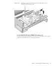
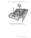
Figure 7-21
Screws for both ends of the XSCF cable connection ports (for the
SPARC M10-4S with a FRAME-A CPU memory unit)
Chapter 7 Maintaining the CPU Memory Units 105


