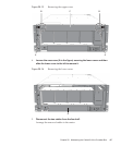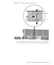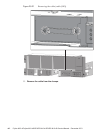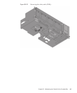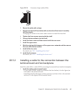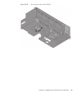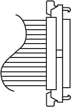
Figure 28-24
Connector shape (cable (SIG))
2.
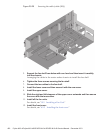
Secure the cable w ith a cla mp.
3.
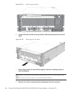
Support the fan shelf from be low with one hand and t hen insert it c arefully
into th e chassis.
Arranging the cables in the center makes it easier to install the fan shelf.
4.
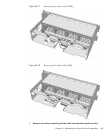
Tighten the three screws securing the fan shelf.
5.
Connect the two cables to t he f an shelf.
6.
Install the lower cover and then secure i t with th e one screw.
7.
Install the upper c over.
8.
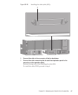
Slide th e right and left stoppers of the upper cover outwards a n d then secur e
the cover w ith the two screws.
9.
Install all the fan units.
For details, see "19.5 Installing a Fan Unit."
10.
Install the front cover.
For details, see "6.5.3 Installing the front cover."
28.5.2 Installing a cable for the connection between the
terminal board and fan backplane
Install the cable (SIG) or cable (PWR) connecting the terminal board and fan backplane.
1.
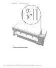
Install the cable on the terminal b o ard.
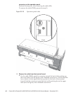
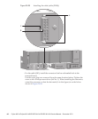
- For the cable (PWR), install the connector that has latches (A in the figure) on
both ends to the terminal board.
Install the tab (B in the figure) of the connector such that it fits in the notched
section (C in the figure) of the terminal board.
Chapter 28 Maintaining the Cable Kit of the Crossbar Box 445


