


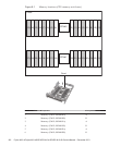
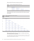
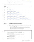

Table 8-1
Memory mounting configurations (CMUL only)
Number of memory
modules
Mounted memory
8ainFigure 8-3 ---
16 a in Figure 8-3 binFigure 8-3 --
24 a in Figure 8-3 binFigure 8-3 einFigure 8-3 -
32 a in Figure 8-3 binFigure 8-3 einFigure 8-3 finFigure 8-3
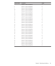
Table 8-2
Memory mounting patterns (CMUL and CMUU)
Number of
memory
modules
Mounted memory
8ain
Figure 8-3
-------
16 a in
Figure 8-3
bin
Figure 8-3
------
24 a in
Figure 8-3
bin
Figure 8-3
cin
Figure 8-3
-----
32 a in
Figure 8-3
bin
Figure 8-3
cin
Figure 8-3
din
Figure 8-3
----
40 a in
Figure 8-3
bin
Figure 8-3
cin
Figure 8-3
din
Figure 8-3
ein
Figure 8-3
---
48 a in
Figure 8-3
bin
Figure 8-3
cin
Figure 8-3
din
Figure 8-3
ein
Figure 8-3
finFigure
8-3
--
56 a in
Figure 8-3
bin
Figure 8-3
cin
Figure 8-3
din
Figure 8-3
ein
Figure 8-3
finFigure
8-3
gin
Figure 8-3
-
64 a in
Figure 8-3
bin
Figure 8-3
cin
Figure 8-3
din
Figure 8-3
ein
Figure 8-3
finFigure
8-3
gin
Figure 8-3
hin
Figure 8-3
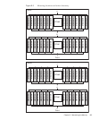
When only the CP U memory unit lower is mounted
When both the CPU memory unit lower and the CPU memory unit upper
are mounted
When expanding a CPU memory unit upper to a chassis in which only a
CPU mem ory unit lower is mounted
If you mount memory by expanding a CPU memory unit upper to a chassis in which
only a CPU memory unit lower is mounted, you do not have to remove the memory
mounted on the CPU memory unit lower.
Fujitsu M10-4/Fujitsu M10-4S/SPARC M10-4/SPARC M10-4S Service Manual
・
December 2013166