A
2.
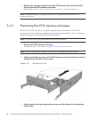
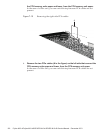
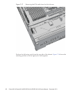
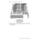
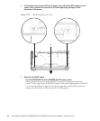
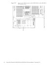
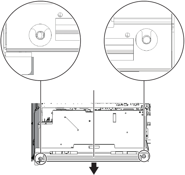
Loosen the tw o screws holding the upper re ar side of the CPU memory u nit
lower. Then, remove th e rear c over ( A in the figure) by pulling i t in the
direction of the a rro w.
Figure 7-22
Removing the rear cover
3.
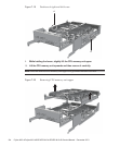
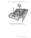
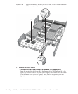
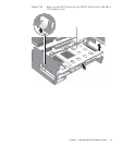
Remove the XSCF board.
-
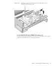
For the SPARC M10-4 with a FRAME-A CPU memory unit
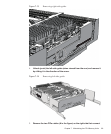
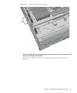
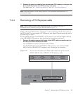
Remove the three screws fixing the XSCF board (A in the figure) and rear
cover. Tilt the right lever of the XSCF mount with your fingers about 5 mm (0.2
in.) to the right (B in the figure). Lift up the right side of the XSCF board and
release the connection of the connector (C in the figure).
Fujitsu M10-4/Fujitsu M10-4S/SPARC M10-4/SPARC M10-4S Service Manual
・
December 2013106


