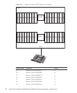
Table 8-4
Types of maintenance for memory (continued)
Configuration Active/hot Active/cold Inactive/hot Inactive/cold (*1) System stopped
Build in g block confi g u rat io n
Unsupported Supported (*2) Unsupported Supported Supported
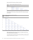
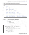
*1: For a single-chassis configuration, the inactive/cold maintenance procedure is the same as that for stopping the system, therefore see
the procedure for system-stopped maintenance.
*2: It is necessary to use dynamic reconfiguration (DR) to disconnect a chassis requiring maintenance from the physical partition.
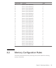
Table 8-5
Maintenance flow
Details of update process Replacement Expansion Reduction
1 Preparation 8.4 8.4 8.4
2 Removing a CPU memory unit 7.4 7.4 7.4
3 Removing memory 8.5 - 8.5
4 Installing memory 8.6 8.6 -
5 InstallingaCPUmemoryunit 7.5 7.5 7.5
6 Restoring the system 8.7 8.7 8.7
8.3.2 Maintenance flow
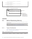
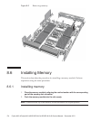
Table 8-5 lists the sequence of the maintenance procedure for memory. The
procedure for expanding memory is the same as that for installing memory. The
procedure for reducing memory is the same as that for removing memory.
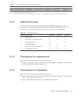
8.3.3 Precautions for replacement
Note the following points when replacing memory:
■
When you replace a memory module, make sure that you install the new module
in the same position as the original one.
8.3.4 Precautions for installation
Note the following points when expanding memory:
■
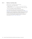
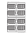
Observe the memory installation rules when you expand memory. For details, see
"8.2.1 Memory mounting rules."
■
Apply XCP 2080 or later when you expand 64 GB memory.
Chapter 8 Maintaining the Memory 169


