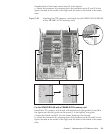
D E
C
B
FG
A
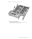
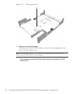
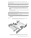
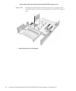
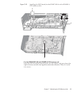
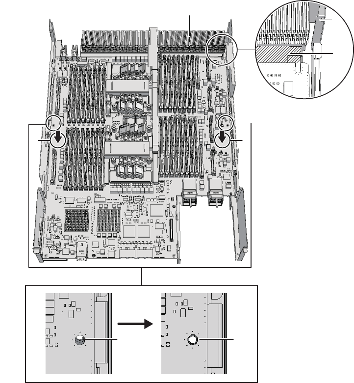
threaded hole of the frame can be seen (E in the figure).
c. Attach the connector by pressing down the connector units (F and G in the
figure) located at the center of the right and left sides of the board at the same
time.
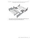
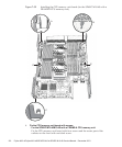
Figure 7-49
Installing the CPU memory unit board (for the SPARC M10-4/M10-4S
with a FRAME-A CPU memory unit)
-
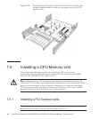
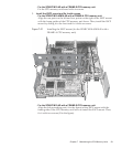
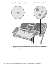
For th e SPARC M10-4S with a FRAM E-B CPU me mory unit
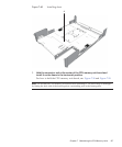
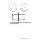
Install the CPU memory unit board with the left and right guides (A and B in
the figure) and the left guide on the board (C in the figure) as a guide.
a. Insert the board carefully into the frame, keeping it horizontal.
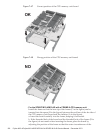
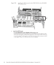
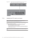
b. Attach the connector by pressing down the connector units (D and E in the
figure) located at the center of the right and left sides of the board at the same
time.
Chapter 7 Maintaining the CPU Memory Units 129


