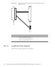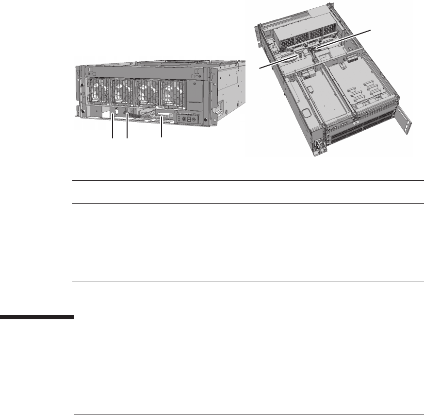
(1)
(2)(3)
(5)
(4)
Location
number
Component Connection
1 Cable (SIG) Crossbar backplane unit and terminal board (SIG)
2 Cable (PWR) Crossbar backplane unit and terminal board (PWR)
3Terminalboard
4 Cable (SIG) Terminal board (SIG) and fan backplane
5 Cable (PWR) Terminal board (PWR) and fan backplane
Note -
Read and understand the instructions in this chapter before starting the maintenance
work. Also see the contents of "Chapter 1 Before Starting Maintenance Work."
Figure 28-5
Locations for the cable kit
28.2 Before Maintaining the Cable Kit
This section describes the types and the flow of maintenance of the cable kit.
28.2.1 Types of maintenance
Table 28-1 lists the types of maintenance for the cable kit. For the definition of
maintenance, see "4.3 Understanding Types of Maintenance."
Chapter 28 Maintaining the Cable Kit of the Crossbar Box 429


