Figure 15-2
Screws securing the mounting frame
7.
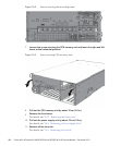
Loosen the scre w securing the CPU m emory unit and lower t h e right and left
levers to the horizontal position.
Figure 15-3
Screw securing CPU memory unit
8.
Pull o ut the CP U memory uni t by abo ut 10 c m (3.9 in.)
9.
Remove the front cover.
For details, see "5.5.3 Removing the front cover."
10.
Pull o ut the power supply u nit by about 10 cm ( 3.9 in.)
For details, see "10.4 Removing a Power Supply Unit."
11.
Remove all the fan units.
For details, see "11.4 Removing a Fan Unit."
Fujitsu M10-4/Fujitsu M10-4S/SPARC M10-4/SPARC M10-4S Service Manual
・
December 2013288


