Note -
Make a note of the positions of the cables connected to the external interface before
disconnecting them to ensure that they are reinstalled correctly.
Note -
Make a note of the positions of the PCIe card cassettes before removing them to ensure
that they are reinstalled correctly.
Note -
If no crossbar unit is mounted, proceed to step 6.
14.4.1 Accessing the PSU backplane unit
1.
Lower the c able support.
For details, see "5.5.1 Lowering the cable support."
2.
Remove all the cable s connected t o the extern al interface.
The cables to be removed are as follows.
■
Interface cable connected to the PCI Express (PCIe) card
■
Crossbar cable
■
XSCF BB control cable
■
XSCF DUAL control cable
■
LAN cable
3.
Remove all PCIe card cassettes.
For details, see "13.5.2 Removing a PCI Express card cassette."
4.
Remove all the crossb ar units.
For details, see "9.4.2 Removing a crossbar unit."
5.
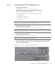
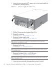
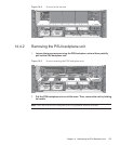
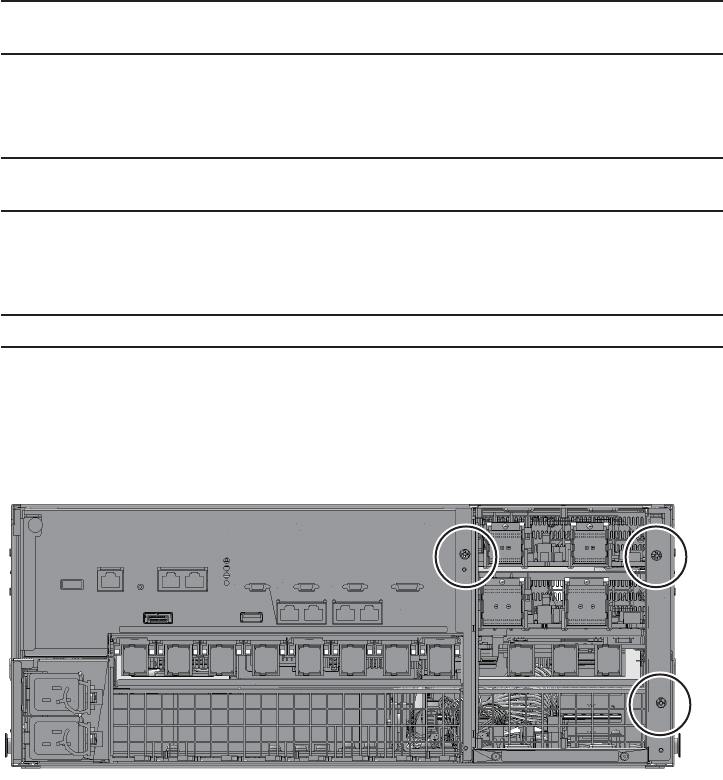
Loosen the three screws securing the mounting fra me of the crossbar u nit
and t h en remove the f ram e.
Figure 14-2
Screws securing the mounting frame
Chapter 14 Maintaining the PSU Backplane Unit 271


