


Note -
If the CPU memory unit lower is inserted as far as it will go, it may not be possible to
lift the lever. Lift the lever just before the CPU memory unit lower hits the rear and then
push it fully home.
Note -
Reinstall the PCIe card cassettes in their original positions by referring to the notes
that you made prior to the start of maintenance.
7.5.3 Installing the CPU memory unit lower
1.
Install the CPU memory unit upper or a filler u nit for a CPU m emory unit
upper.
For details, see "7.5.2 Installing the CPU memory unit upper."
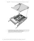
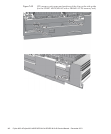
2.
Insert the CPU me mory unit low er into the chassis while supporting it from
below w ith o ne ha nd.
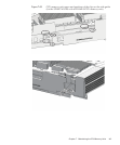
3.
Raise th e right an d left l evers o f the CP U memory unit lo w er to s ecure it.
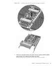
7.5.4 Restoring the chassis
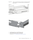
1.
If a crossbar unit was m ou nted, install th e mounting fr ame and t hen tighten
the t hree screws.
2.
If any crossbar units were mounted, rei nstall all of t he m.
For details, see "9.5 Installing a Crossbar Unit."
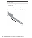
3.
Install all the PCIe card c as settes.
For details, see "13.6.2 Installing a PCI Express card cassette."
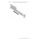
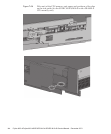
4.
Connect all t he cables f or the external interface.
The cables to be connected are as follows.
■
Interface cable connected to the PCIe card
■
Crossbar cables (If equipment rack model 26xx or equipment rack model 16xx
is used, connect them in step 6.)
■
XSCF BB control cable
■
XSCF DUAL control cable
■
XSCF-LAN cable
■
Serial cable
■
LAN cable
■
SAS cable
■
USB cable
Fujitsu M10-4/Fujitsu M10-4S/SPARC M10-4/SPARC M10-4S Service Manual
・
December 2013146