


User’s Manual
IBM PowerPC 750GX and 750GL RISC Microprocessor
Instruction Timing
Page 232 of 377
gx_06.fm.(1.2)
March 27, 2006
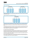
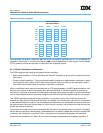
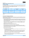
2. In clock cycle 1, instructions 2 and 3 enter the dispatch entries in the IQ. Instruction 4 (a second bc
instruction) and 5 are fetched. The second bc instruction is predicted as taken. It can be folded, but it
cannot be resolved until instruction 3 writes back.
3. In clock cycle 2, instruction 4 has been folded and instruction 5 has been flushed from the IQ. The two
target instructions, T0 and T1, are both in the BTIC, so they are fetched in this cycle. Note that, even
though the first bc instruction might not have resolved by this point (we can assume it has), the 750GX
allows fetching from a second predicted branch stream. However, these instructions could not be dis-
patched until the previous branch has resolved.
4. In clock cycle 3, target instructions T2–T5 are fetched as T0 and T1 are dispatched.
5. In clock cycle 4, instruction 3, on which the second branch instruction depended, writes back, and the
branch prediction is proven incorrect. Even though T0 is in CQ1, from which it could be written back, it is
not written back because the branch prediction was incorrect. All target instructions are flushed from their
positions in the pipeline at the end of this clock cycle, as are any results in the Rename Registers.
After one clock cycle required to refetch the original instruction stream, instruction 5, the same instruction that
was fetched in clock cycle 1, is brought back into the IQ from the instruction cache, along with three others
(not all of which are shown).
6.4.2 Integer Unit Execution Timing
The
750GX has two integer units. The IU1 can execute all integer instructions; the IU2 can execute all integer
instructions except multiply and divide instructions. As shown in Figure 6-2 on page 212, each integer unit
has one execute pipeline stage. Thus, when a multicycle (for example, divide) integer instruction is being
executed, no additional integer instruction can begin to execute in that unit. However, the other unit IU2 can
continue to execute integer instructions. Table 6-7 on page 240 lists integer instruction latencies. Most
integer instructions have an execution latency of one clock cycle.
6.4.3 Floating-Point Unit Execution Timing
The floating-point unit on the 750GX executes all floating-point instructions. Execution of most floating-point
instructions is pipelined within the FPU, allowing up to three instructions to execute in the FPU concurrently.
While most floating-point instructions execute with 3-cycle or 4-cycle latency, and 1-cycle or 2-cycle
throughput, two instructions, fdivs and fdiv, execute with latencies of 11 to 33 cycles. The following instruc-
tions block the floating-point unit pipeline until they complete execution:
• Floating Divide Single (fdivs)
• Floating Divide (fdiv)
• Move-to Floating-Point Status and Control Register [FPSCR] Bit 0 (mtfsb0)
• Move-to FPSCR Bit 1(mtfsb1)
• Move-to FPSCR Field Immediate (mtfsfi)
• Move-from FPSCR (mffs)
• Move-to FPSCR Fields (mtfsf)
Thus, they inhibit the dispatch of additional floating-point instructions. See Table 6-8 on page 242 for floating-
point instruction execution timing.
6.4.4 Effect of Floating-Point Exceptions on Performance
For the fastest and most predictable floating-point performance, all exceptions should be disabled in the
FPSCR and Machine State Register (MSR).