


User’s Manual
IBM PowerPC 750GX and 750GL RISC Microprocessor
gx_07.fm.(1.2)
March 27, 2006
Signal Descriptions
Page 249 of 377
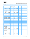
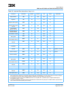
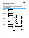
7. Signal Descriptions
This chapter describes the 750GX microprocessor’s external signals. It contains a concise description of indi-
vidual signals, showing behavior when the signal is asserted and negated and when the signal is an input and
an output.
Note: A bar over a signal name indicates that the signal is active low—for example, ARTRY
(address retry)
and TS
(transfer start). Active-low signals are referred to as asserted (active) when they are low and negated
when they are high. Signals that are not active low, such as A[0–31] (address-bus signals) and TT[0–4]
(transfer type signals) are referred to as asserted when they are high and negated when they are low.
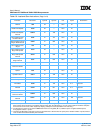
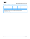
The 750GX’s signals are grouped as follows:
Address arbitration The 750GX uses these signals to arbitrate for address-bus mastership.
Address transfer start Indicate that a bus master has begun a transaction on the address bus.
Address transfer These signals include the address bus. They are used to transfer the address.
Transfer attribute Provide information about the type of transfer, such as the transfer size and
whether the transaction is burst, write-through, or cache-inhibited.
Address transfer
termination
Acknowledge the end of the address phase of the transaction. They also indicate
whether a condition exists that requires the address phase to be repeated.
Data arbitration The 750GX uses these signals to arbitrate for data-bus mastership.
Data transfer These signals, which consist of the data bus, are used to transfer the data.
Data-transfer
termination
Data termination signals are required after each data beat in a data transfer. In a
single-beat transaction, the data termination signals also indicate the end of the
tenure; while in burst accesses, the data termination signals apply to individual
beats and indicate the end of the tenure only after the final data beat. They also
indicate whether a condition exists that requires the data phase to be repeated.
Interrupts/resets These signals include the external interrupt signal, checkstop signals, and both soft
reset and hard reset signals. They are used to interrupt and, under various condi-
tions, to reset the processor.
Processor status and
control
These signals are used to set the reservation coherency bit, enable the time base,
and for other functions. They are also used in conjunction with such resources as
secondary caches and the time-base facility.
Clock control Determine the system clock frequency. These signals can also be used to synchro-
nize multiprocessor systems.
Test interface The Joint Test Action Group (JTAG) (IEEE 1149.1a-1993) interface and the
common on-chip processor (COP) unit provide a serial interface to the system for
performing board-level boundary-scan interconnect tests.