


User’s Manual
IBM PowerPC 750GX and 750GL RISC Microprocessor
gx_02.fm.(1.2)
March 27, 2006
Programming Model
Page 59 of 377
The PowerPC UISA registers are user-level. General Purpose Registers (GPRs) and Floating Point Registers
(FPRs) are accessed through instruction operands. Access to registers can be explicit (by using instructions
for that purpose such as mtspr and mfspr instructions) or implicit as part of the execution of an instruction.
Some registers are accessed both explicitly and implicitly.
Implementation Note: The 750GX fully decodes the SPR field of the instruction. If the SPR specified is
undefined, an illegal instruction program exception occurs.
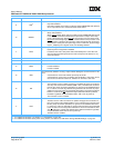
Descriptions of the PowerPC user-level registers follow:
• User-level registers (UISA)—The user-level registers can be accessed by all software with either user
or supervisor privileges. They include the following registers:
– General Purpose Registers (GPRs). The 32 GPRs (GPR0–GPR31) serve as data source or destina-
tion registers for integer instructions and provide data for generating addresses. See “General Pur-
pose Registers (GPRs)” in Chapter 2, “PowerPC Register Set” of the PowerPC Microprocessor
Family: The Programming Environments Manual for more information.
– Floating Point Registers (FPRs). The 32 FPRs (FPR0–FPR31) serve as the data source or destina-
tion for all floating-point instructions. See “Floating Point Registers (FPRs)” in Chapter 2, “PowerPC
Register Set” of the PowerPC Microprocessor Family: The Programming Environments Manual.
– Condition Register (CR). The 32-bit CR consists of eight 4-bit fields, CR0–CR7, that reflect results of
certain arithmetic operations and provide a mechanism for testing and branching. See “Condition
Register (CR)” in Chapter 2, “PowerPC Register Set” of the PowerPC Microprocessor Family: The
Programming Environments Manual.
– Floating-Point Status and Control Register (FPSCR). The FPSCR contains all floating-point excep-
tion signal bits, exception summary bits, exception enable bits, and rounding control bits needed for
compliance with the IEEE 754-1985 standard. See “Floating-Point Status and Control Register
(FPSCR)” in Chapter 2, “PowerPC Register Set” of the PowerPC Microprocessor Family: The Pro-
gramming Environments Manual.
The remaining user-level registers are SPRs. Note that the PowerPC Architecture provides a separate
mechanism for accessing SPRs (the mtspr and mfspr instructions). These instructions are commonly
used to explicitly access certain registers, while other SPRs are more typically accessed as the side
effect of executing other instructions.
– Integer Exception Register (XER). The XER indicates overflow and carries for integer operations.
See “XER Register (XER)” in Chapter 2, “PowerPC Register Set” of the PowerPC Microprocessor
Family: The Programming Environments Manual for more information.
Implementation Note: To allow emulation of the Load String and Compare Byte Indexed (lscbx)
instruction defined by the POWER architecture, XER[16–23] is implemented so that it can be read
with mfspr and written with Move-to Fixed-Point Exception Register (mtxer) instructions.
– Link Register (LR). The LR provides the branch target address for the Branch Conditional to Link
Register (bclrx) instruction, and can be used to hold the logical address of the instruction that follows
a branch and link instruction, typically used for linking to subroutines. See “Link Register (LR)” in
Chapter 2, “PowerPC Register Set” of the PowerPC Microprocessor Family: The Programming Envi-
ronments Manual.
– Count Register (CTR). The CTR holds a loop count that can be decremented during execution of
appropriately coded branch instructions. The CTR can also provide the branch target address for the
Branch Conditional to Count Register (bcctrx) instruction. See “Count Register (CTR)” in Chapter 2,