


User’s Manual
IBM PowerPC 750GX and 750GL RISC Microprocessor
Programming Model
Page 60 of 377
gx_02.fm.(1.2)
March 27, 2006
“PowerPC Register Set” of the PowerPC Microprocessor Family: The Programming Environments
Manual.
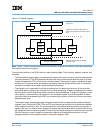
• User-level registers (VEA)—The PowerPC VEA defines the time-base facility (TB), which consists of
two 32-bit registers—Time Base Upper (TBU) and Time Base Lower (TBL). The Time Base Registers can
be written to only by supervisor-level instructions, but can be read by both user-level and supervisor-level
software. For more information, see “PowerPC VEA Register Set—Time Base” in Chapter 2, “PowerPC
Register Set” of the PowerPC Microprocessor Family: The Programming Environments Manual.
• Supervisor-level registers (OEA)—The OEA defines the registers an operating system uses for mem-
ory management, configuration, exception handling, and other operating system functions. The OEA
defines the following supervisor-level registers for 32-bit implementations:
– Configuration registers
• Machine State Register (MSR). The MSR defines the state of the processor. The MSR can be
modified by the Move-to Machine State Register (mtmsr), System Call (sc), and Return from
Exception (rfi) instructions. It can be read by the Move-from Machine State Register (mfmsr)
instruction. When an exception is taken, the contents of the MSR are saved to the Machine Sta-
tus Save/Restore Register 1 (SRR1), which is described below. See “Machine State Register
(MSR)” in Chapter 2, “PowerPC Register Set” of the PowerPC Microprocessor Family: The Pro-
gramming Environments Manual for more information.
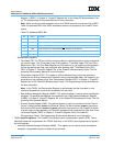
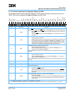
Implementation Note: Table 2-1 describes MSR bits the 750GX implements that are not
required by the PowerPC Architecture.
Note: Setting MSR[EE] masks not only the architecture-defined external interrupt and decre-
menter exceptions, but also the 750GX-specific system management, performance-monitor, and
thermal-management exceptions.
• Processor Version Register (PVR). This register is a read-only register that identifies the version
(model) and revision level of the PowerPC processor. For more information, see “Processor Ver-
sion Register (PVR)” in Chapter 2, “PowerPC Register Set” of the PowerPC Microprocessor
Family: The Programming Environments Manual.
Note: The Processor Version Number is x’7002’ for the 750GX. The processor revision level will
start at x’0100’ and will be incremented for each revision of the chip.
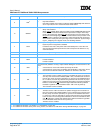
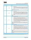
Table 2-1. Additional MSR Bits
Bit Name Description
13 POW
Power management enable. Optional in the PowerPC Architecture.
0 Power management is disabled.
1 Power management is enabled.
The processor can enter a power-saving mode when additional conditions are present. The mode
chosen is determined by the DOZE, NAP, and SLEEP bits in the Hardware-Implementation-
Dependent Register 0 (HID0), described in Section 2.1.2.2 on page 65.
To set the POW bit, see Table 10-2, HID0 Power Saving Mode Bit Settings, on page 337. The
750GX will clear the POW bit when it leaves a power saving mode.
29 PM
Performance-monitor marked mode. This bit is specific to the 750GX, and is defined as reserved by
the PowerPC Architecture. See Chapter 10, Power and Thermal Management, on page 335.
0 Process is not a marked process.
1 Process is a marked process.
The MSR[PM]
bit is used by the Performance-Monitor to help determine when it should count
events. For a description of the Performance-Monitor, see Chapter 11, Performance Monitor and
System Related Features, on page 349.