


User’s Manual
IBM PowerPC 750GX and 750GL RISC Microprocessor
Power and Thermal Management
Page 344 of 377
gx_10.fm.(1.2)
March 27, 2006
The TAU provides thermal control by periodically comparing the 750GX’s junction temperature against user-
programmed thresholds, and generating a thermal-management interrupt if the threshold values are crossed.
The TAU also enables the user to determine the junction temperature through a software successive approx-
imation routine.
The TAU is controlled through four supervisor-level SPRs, accessed through the Move-to Special Purpose
Register (mtspr) and Move-from Special Purpose Register (mfspr) instructions. Two of the SPRs (THRM1
and THRM2) provide temperature threshold values that can be compared to the junction temperature value,
and control bits that enable comparison and thermal interrupt generation. The third SPR (THRM3) provides a
TAU enable bit and a sample interval timer. To enhance accuracy, THRM4 provides the temperature offset
measured and burned into the THRM4 Register at the factory.
Note that all the bits in THRM1, THRM2, and THRM3 are cleared to 0 during a hard reset. THRM4 always
contains the fused offset value determined at the factory. The TAU remains idle and in a low-power state until
configured and enabled.
The bit fields of THRM1 and THRM2 are described in Section 2.1.4.1, Thermal-Management Registers 1–2
(THRM1–THRM2), on page 78. The bit fields of THRM3 are described Section 2.1.4.2, Thermal-Manage-
ment Register 3 (THRM3), on page 79. The bit fields of THRM4 are described on Section 2.1.4.3, Thermal-
Management Register 4 (THRM4), on page 80.
10.4.2 Thermal Assist Unit Operation
The TAU can be programmed to operate in single-threshold or dual-threshold modes, which results in the
TAU generating a thermal-management interrupt when one or both threshold values are crossed. In addition,
with the appropriate software routine, the TAU can also directly determine the junction temperature. The
following sections describe the configuration of the TAU to support these modes of operation.
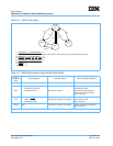
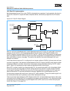
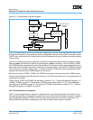
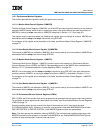
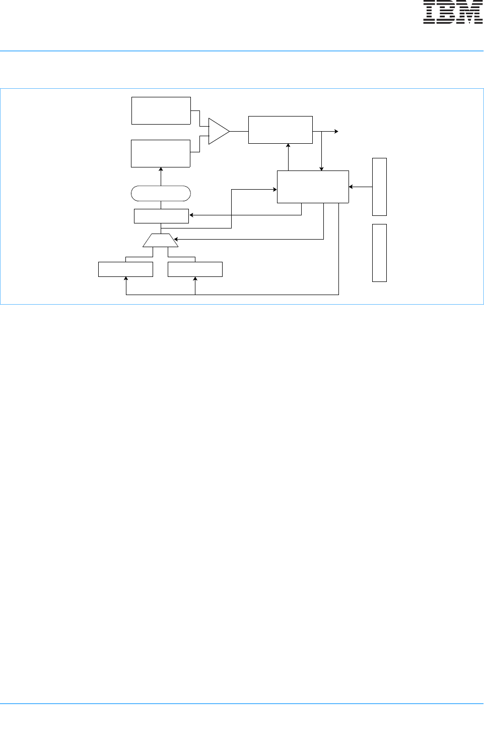
Figure 10-4. Thermal Assist Unit Block Diagram
Thermal Sensor
Thermal Sensor
Control Logic
DAC
Decoder
Latch
Interrupt Control
THRM1 THRM2
THRM3
Thermal Interrupt
Request
(0x1700)
THRM4