


User’s Manual
IBM PowerPC 750GX and 750GL RISC Microprocessor
gx_02.fm.(1.2)
March 27, 2006
Programming Model
Page 63 of 377
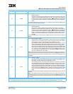
– Hardware-Implementation-Dependent Register 0 (HID0)—This register controls various functions,
such as enabling checkstop conditions, and locking, enabling, and invalidating the instruction and
data caches, power modes, miss-under-miss, and others.
– Hardware-Implementation-Dependent Register 1 (HID1)—This register reflects the state of
PLL_CFG[0:4] clock signals, and phase-locked loop (PLL) selection and range bits.
– Hardware-Implementation-Dependent Register 2 (HID2)—This register controls parity enablement.
– L2 Cache Control Register (L2CR)—This register is used to configure and operate the L2 cache.
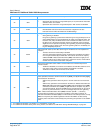
– Performance-monitor registers. The following registers are used to define and count events for use
by the performance monitor:
• The Performance-Monitor Counter Registers (PMC1–PMC4) are used to record the number of
times a certain event has occurred. UPMC1–UPMC4 provide user-level read access to these
registers.
• The Monitor Mode Control Registers (MMCR0–MMCR1) are used to enable various perfor-
mance-monitor interrupt functions. UMMCR0–UMMCR1 provide user-level read access to these
registers.
• The Sampled Instruction Address Register (SIA) contains the effective address of an instruction
executing at or around the time that the processor signals the performance-monitor interrupt con-
dition. USIA provides user-level read access to the SIA.
• The 750GX does not implement the Sampled Data Address Register (SDA) or the user-level,
read-only USDA registers. However, for compatibility with processors that do, those registers can
be written to by boot code without causing an exception. SDA is SPR 959; USDA is SPR 943.
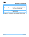
– Instruction Cache Throttling Control Register (ICTC)—This register has bits for enabling the instruc-
tion-cache throttling feature and for controlling the interval at which instructions are forwarded to the
instruction buffer in the fetch unit. This provides control over the processor’s overall junction temper-
ature.
– Thermal-Management Registers (THRM1, THRM2, THRM3, and THRM4)—Used to enable and set
thresholds for the thermal-management facility.
• THRM1 and THRM2 provide the ability to compare the junction temperature against two user-
provided thresholds. The dual thresholds allow the thermal-management software differing
degrees of action in lowering the junction temperature. The TAU can be also operated in a single-
threshold mode in which the thermal sensor output is compared to only one threshold in either
THRM1 or THRM2.
• THRM3 is used to enable the thermal-management assist unit (TAU) and to control the compara-
tor output sample time.
• THRM4 is a read-only register containing a temperature offset (determined at the factory) applied
to junction temperature measurements for improved accuracy.
Note: While it is not guaranteed that the implementation of 750GX-specific registers is consistent among
PowerPC processors, other processors may implement similar or identical registers.