


User’s Manual
IBM PowerPC 750GX and 750GL RISC Microprocessor
Programming Model
Page 78 of 377
gx_02.fm.(1.2)
March 27, 2006
2.1.4 Thermal-Management Registers (THRMn)
The on-chip thermal-management assist unit provides the following functions:
• Compares the junction temperature against user programmed thresholds
• Generates a thermal-management interrupt if the temperature crosses the threshold
• Provides a way for a successive approximation routine to estimate junction temperature
Control and access to the thermal-management assist unit is through the privileged mtspr and mfspr instruc-
tions to the four THRM registers.
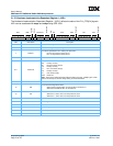
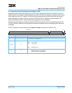
2.1.4.1 Thermal-Management Registers 1–2 (THRM1–THRM2)
THRM1 and THRM2 provide the ability to compare the junction temperature against two user-provided
thresholds. Having dual thresholds allows thermal-management software differing degrees of action in
reducing junction temperature. Thermal management can use a single-threshold mode in which the thermal
sensor output is compared to only one threshold in either THRM1 or THRM2.
If an mtspr affects a THRM register that contains operating parameters for an ongoing comparison during
operation of the thermal assist unit, the respective TIV bits are cleared and the comparison is restarted.
Changing THRM3 forces the TIV bits of both THRM1 and THRM2 to 0, and restarts the comparison if
THRM3[E] is set (see Section 2.1.4.2 on page 79).
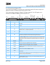
Examples of valid THRM1/THRM2 bit settings are shown in Table 2-3 on page 79.
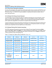
TIN
TIV
THRESHOLD Reserved
TID
TIE
V
012345678910111213141516171819202122232425262728293031
Bits Field Name Description
0TIN
Thermal-management interrupt bit. Read only. This bit is set if the thermal sensor output
crosses the threshold specified in the SPR. The state of this bit is valid only if TIV is set.
The interpretation of the TIN bit is controlled by the TID bit. See Table 2-3.
1TIV
Thermal-management interrupt valid. Read only. This bit is set by the thermal assist logic
to indicate that the thermal-management interrupt (TIN) state is valid. See Table 2-3.
2:8 THRESHOLD
Threshold that the thermal sensor output is compared to. The range is 0°–127°C in incre-
ments of 1°C. Note that this is not the resolution of the thermal sensor.
9:28 Reserved Reserved. System software should clear these bits when writing to the THRMn SPRs.
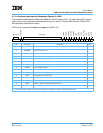
29 TID
Thermal-management interrupt direction bit. Selects the result of the temperature com-
parison to set TIN and to assert a thermal-management interrupt if TIE is set. If TID is
cleared, TIN is set and an interrupt occurs if the junction temperature exceeds the thresh-
old. If TID is set, TIN is set and an interrupt is indicated if the junction temperature is
below the threshold. See Table 2-3.
30 TIE
Thermal-management interrupt enable. Enables assertion of the thermal-management
interrupt signal. The thermal-management interrupt is maskable by the MSR[EE] bit. If
TIE is cleared and THRMn is valid, the TIN bit records the status of the junction tempera-
ture versus threshold comparison without causing an exception. This feature allows sys-
tem software to make a successive approximation to estimate the junction temperature.
See Table 2-3 on page 79.
31 V
SPR valid bit. Setting this bit indicates that the SPR contains a valid threshold, TID, and
TIE control bit. Setting THRM1/2[V] and THRM3[E] to 1 enables operation of the thermal
sensor. See Table 2-3 on page 79.